Network Kings

Multi-Access Year Deal

Get 55+ courses now at the best price ever! Use Code:    MULTIYEAR

d :
h :
m

What is a Routing Table in Computer Networks?

what is a Routing Table?

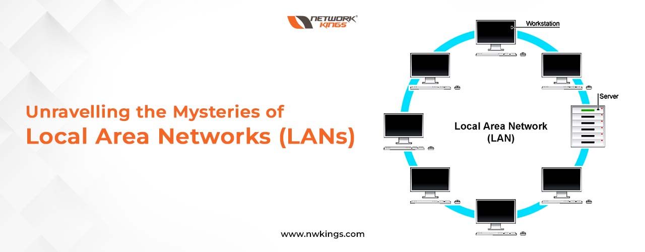
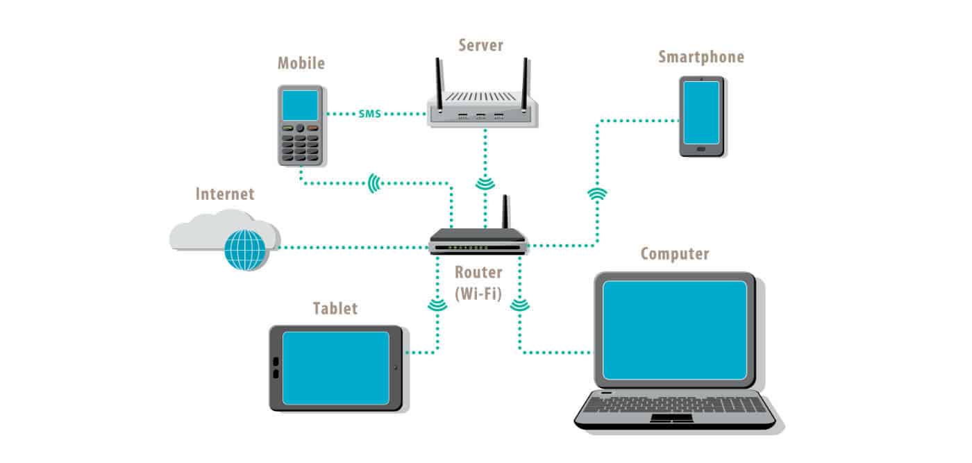
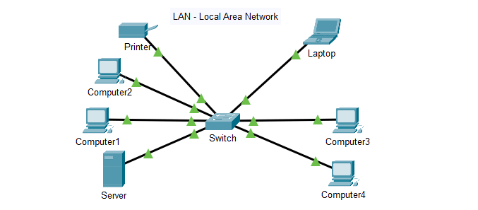
Until now, we have also learned about the network components such as routers and Wireless LANs. When you grant Internet access, your LAN is connected to the Internet via the router.

Therefore, a router plays a very important role in forwarding the data packets in a computer network. It is the one responsible for sending your packets from source to destination.

Note: If you haven’t read the previous blog of our CCNA 200-301 series, I highly recommend you do so.  

In this blog, we will learn how a router uses a ‘routing table’ , the interface to which the data must be sent. We will also learn about all the information that a routing table stores inside it. Last but not the least, we will also learn the difference between static and dynamic routing.

Let us start learning about the routing table!

Devices such as routers and switches that are IP-enabled use routing tables. A routing table is updated dynamically via network routing protocols.

What is a routing table?

When a data packet has to be sent to a destination via the source, the router delivers the packet by following a set of rules. These sets of rules viewed in a tabular format determine where these data packets will be delivered. These are called a routing table.

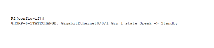
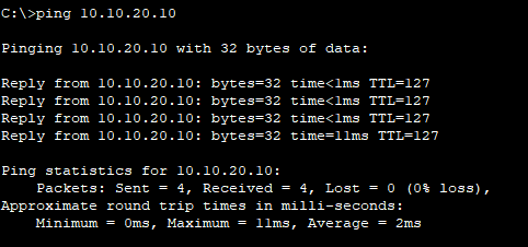
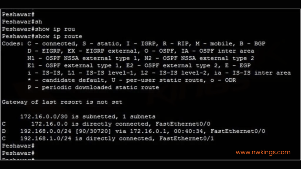
You can view a routing table by using the “show IP route” command. When you use this command, you will be presented by something like the following:

show ip route” command.

Devices such as routers and switches that are IP-enabled use routing tables. A routing table is updated dynamically via network routing protocols.

How Does a Routing Table Work?

A router has to make decisions on which interface it has to deliver the packets. A routing table helps the router to take these decisions effectively.

The routing table helps a router with the following most important piece of information:

  • It tells the destination IP address to the router.
  • It tells the best path to the router to reach the destination.
  • It also helps the router to manage the network traffic every second.
routing table

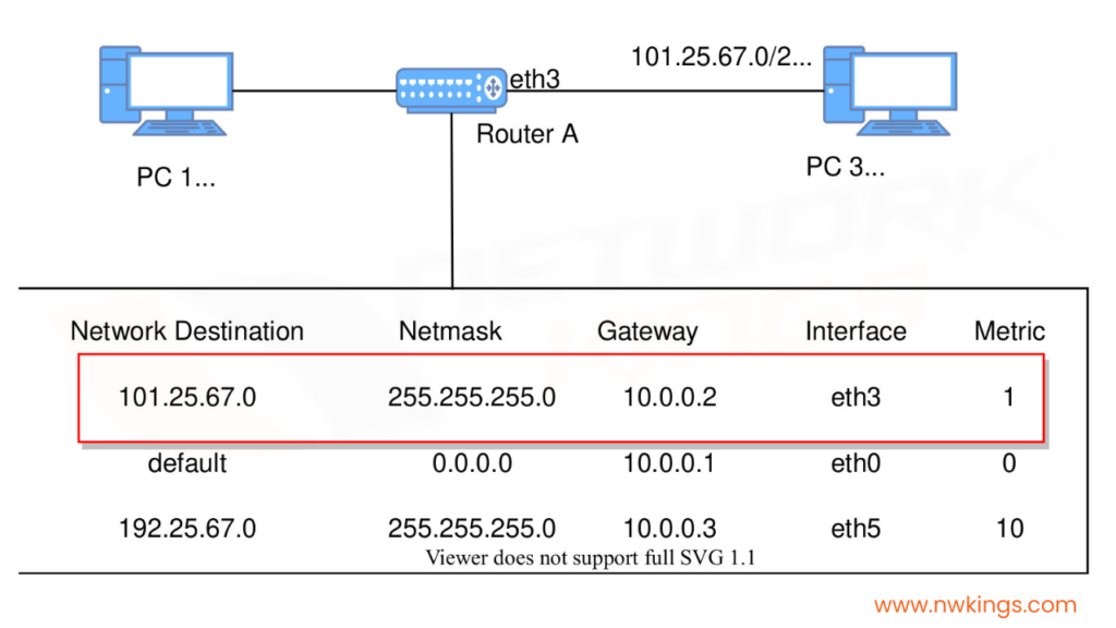
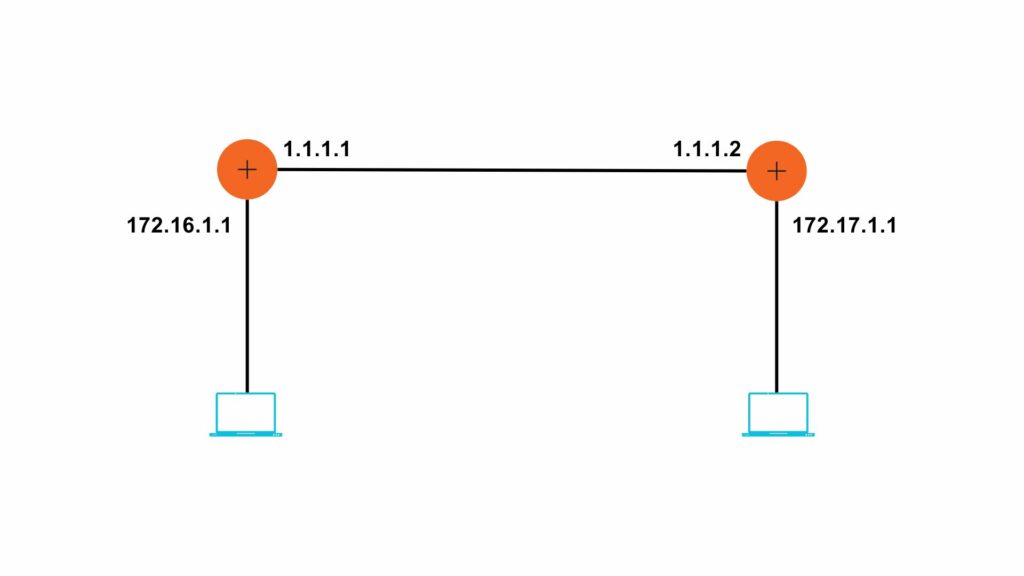
In the routing table as shown in the image above, the 3 metrics are the most important:

  • Network destination:

It consists of the network ID of the destination. 

  • Net mask:

It consists of the subnet mask of the destination IP address.

  • Interface:

It refers to the port at which the router is connected to the network.

Let’s understand all of these in detail!

What are the Routing Table Entries?

Routing table entries refer to the information that is contained in a routing table. It contains important information such as IPv4 and IPv6 address classes. 

Note: The primary fields such as Network ID, next hop and cost or metric of a routing table do not change.

Let us learn about the various routing table entries:

  • Network ID:

The Network ID is the ID of the destination that belongs to a route.

  • Destination:

It is the IP address of the final destination that a data packet has to reach.

  • Subnet Mask:

It is a 32-bit network address, also referred to as the netmask. It functions to match the destination IP Address to the Network ID. it tells whether the host is the local or remote network. 

  • Gateway:

It is the IP address to which the packet is forwarded to and is commonly known as the next hop.

  • Interface:

A router could either be connected to the devices in the same network or outside a Wide Area Network (WAN). They mostly use Ethernet interfaces to connect to these devices. 

  • Metric:

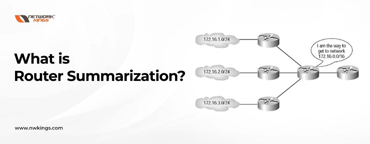
It shows the minimum number of networks crosses or hops to the Network ID. it provides a value to each available route through which the packet can be sent. Then, it helps in selecting the best path. 

The path with the lowest metric is chosen when there are multiple paths to the same destination network.

How are the Routing Tables Maintained?

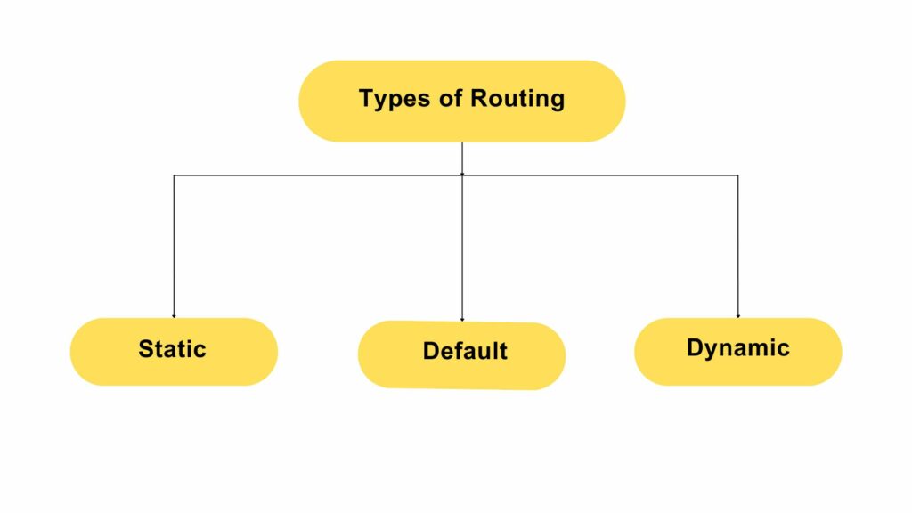
A routing table can be maintained by:

  • Using Dynamic routing
  • Using Static routing

Let’s learn the difference between these two routing modes with the help of a table!

Dynamic Routing 

Static Routing

1. Routing protocols are used to build and maintain the routing tables automatically without any manual help.

1. The routing tables are not changed until a Network Administrator manually changes them.

2. They have multiple paths available to the destination.

2. They have a single pre-configured path to the destination.

3. The algorithms automatically update the routing tables.

3. There is no automation update.

4. It needs more computation time and bandwidth.

4. It does not need more computation time or bandwidth.

5. It is less secure.

5. It is more secure.

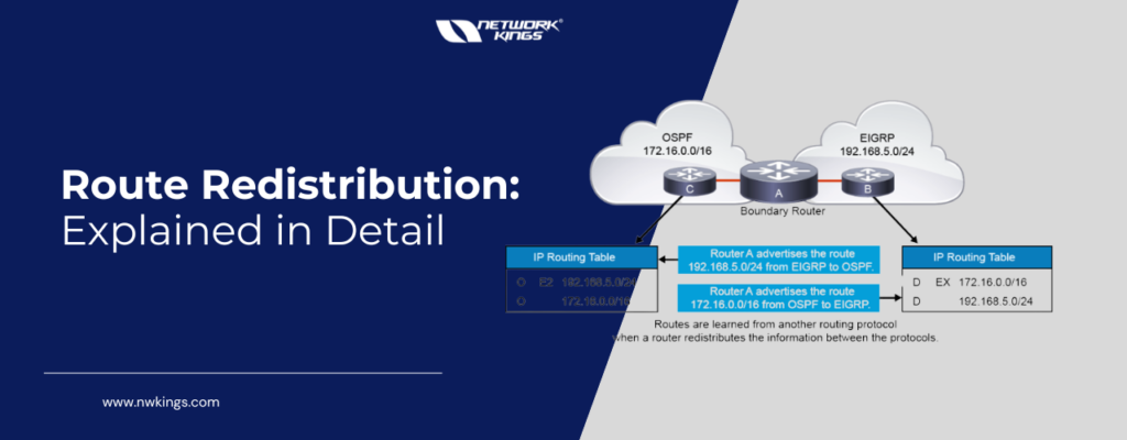
6. It uses distance vector algorithms such as RIP/IGRP as well as link state algorithms such as OSPF to adjust the routes.

6. There is no use of algorithms.

7. Entire routing table is used to identify the available paths.

7. Only one entry in the routing table is used to identify the available path.

8. It is used in large networks in big organizations.

8. It is used in small networks in small-sized organizations.

The above are all the important points that you need to know about static and dynamic routing.

Conclusion:

This marks the end of our introductory blog to the routing table. We have learned about what routing tables are and how they function.

This helps us understand and dissect how routers work. We also learned about how routing tables can be maintained. Further, we will learn more about networks in the upcoming blogs. 

Stay tuned for the upcoming blog of our CCNA 200-301 series. 

Happy Learning.

Types of Routing Protocols – Explained 

types of routing
types of routing

Routing is a process of selecting the best possible paths for data packets to travel from a source to a destination in a network. Routing is performed by layer 3 devices like routers and multi-layer switches. 

What are the different types of Routing?

Routing protocols can be broadly categorized into three types:-  

  1. Static Routing  
  2. Default Routing  
  3. Dynamic Routing  

Let us try to understand each type in brief. 

What is Static Routing Protocol?

Static Routing is a process in which the network administrator will determine the path to reach unknown networks. So, in the case of static routing, the network administrator will configure the router’s routing table manually.  

In case any change occurs in a network, the administrator has to reconfigure the route, and changes do not take place automatically. Static routing is simple to configure and suitable for small-scale enterprises. 

How to configure Static Routing?

Static Routing can be configured in two ways, namely- 

  • Static Routing with the Next Hop 

In this type of static routing, the network administrator will tell the router about the next hop address, i.e., the neighboring router interface IP to reach a particular network. 

Syntax for static routing with the next hop: 

Enter Global configuration mode. 

Device# configure terminal

Device (config)# ip route <Destination N/W IP> <Destination subnet mask> <Next hop IP address> 

  • Static Routing with an Exit Interface 

In this case, the network administrator will configure the router about the interface from which a packet will exit for an unknown network. Most commonly, this protocol is used when routers are connected with a serial cable. The serial cable does not use the Mac address. 

NOTE: If Mac addresses are not used, then proxy ARP will not be generated.   

Syntax for static routing with an exit interface: 

Enter Global configuration mode. 

Device# configure terminal

Device(config)# ip route <Destination N/W IP> <Destination Subnet Mask> <Exit interface> 

Configuration:- Let us take an example of a small topology given in the figure. 

R1 


Shape 

R1#config t 

R1(config)#ip route 172.17.0.0 255.255.0.0 1.1.1.2 


R2 


R2#config t 

R2(config)#ip route 172.16.0.0 255.255.0.0 1.1.1.1 


Verification: – 


R1#show ip route  

Codes:

L – local, C – connected, S – static, R – RIP, M – mobile, B – BGP

D – EIGRP, EX – EIGRP external, O – OSPF, IA – OSPF inter area

N1 – OSPF NSSA external type 1, N2 – OSPF NSSA external type 2

E1 – OSPF external type 1, E2 – OSPF external type 2, E – EGP

i – IS-IS, L1 – IS-IS level-1, L2 – IS-IS level-2, ia – IS-IS inter area

* – candidate default, U – per-user static route, o – ODR

P – periodic downloaded static route 


The Gateway of last resort is not set.

1.0.0.0/8 is variably subnetted, 2 subnets, 2 masks 

C 1.0.0.0/8 is directly connected, GigabitEthernet0/0/0 

L 1.1.1.1/32 is directly connected, GigabitEthernet0/0/0 172.16.0.0/16 is variably subnetted, 2 subnets, 2 masks 

C 172.16.0.0/16 is directly connected, GigabitEthernet0/0/1 

L   172.16.1.1/32 is directly connected, GigabitEthernet0/0/1 

S 172.17.0.0/16 [1/0] via 1.1.1.2 


R2#show ip route  

Codes:

L – local, C – connected, S – static, R – RIP, M – mobile, B – BGP 

D – EIGRP, EX – EIGRP external, O – OSPF, IA – OSPF inter area 

N1 – OSPF NSSA external type 1, N2 – OSPF NSSA external type 2 

E1 – OSPF external type 1, E2 – OSPF external type 2, E – EGP 

i – IS-IS, L1 – IS-IS level-1, L2 – IS-IS level-2, ia – IS-IS inter area 

* – candidate default, U – per-user static route, o – ODR 

P – periodic downloaded static route 


The Gateway of last resort is not set. 

1.0.0.0/8 is variably subnetted, 2 subnets, 2 masks 

C 1.0.0.0/8 is directly connected, GigabitEthernet0/0/0 

L 1.1.1.2/32 is directly connected, GigabitEthernet0/0/0 

S 172.16.0.0/16 [1/0] via 1.1.1.1  

172.17.0.0/16 is variably subnetted, 2 subnets, 2 masks 

C 172.17.0.0/16 is directly connected, GigabitEthernet0/0/1 

L 172.17.1.1/32 is directly connected, GigabitEthernet0/0/1 

What are the advantages of Static Routing Protocol?

The advantages of the Static Routing Protocol are as follows:-  

  1. Easy to implement as compared to dynamic routing  
  2. Less overhead on the router means minimizing the utilization of the device.

What are the disadvantages of Static Routing Protocol?

The disadvantages of the Static Routing Protocol are as follows:-  

  1. It is not suitable to configure on a large network because the administration has to configure it manually.  
  2. If there are changes in the network, like a new router being added or a network being removed, then the static entry must be added or removed accordingly.  
  3. Recursive Lookup: When a routing table is checked more than once for a packet, this is known as a recursive lookup. This is a disadvantage with static routing with the next hop. 

What is Default Routing Protocol?

When a router does not have the specific route entry for the destination network, default routing is used to forward packets to a default gateway or next-hop router. In other words, a router will send a packet to a preconfigured default gateway if the packet’s destination IP address doesn’t match any of the routes it has configured.  

NOTE: Default routing is the type of static routing in which all the packets will be forwarded by matching the default entry in the routing table.  

This routing protocol is mainly used at the edge router of the enterprise  

There is a high chance of creating a loop in the network by default routing so we have to use default routing carefully. 

Syntax:  


Enter Global configuration mode. 

Shape 

Device# configure terminal 

Device(config)# ip route 0.0.0.0 0.0.0.0 <Next Hop IP Address> 


Configuration: – Let us configure the default route on the same topology   

R1#config t 

R1(config)#ip route 0.0.0.0 0.0.0.0 1.1.1.2 


Verification: 


R1#show ip route 

Codes: L – local, C – connected, S – static, R – RIP, M – mobile, B – BGP 

D – EIGRP, EX – EIGRP external, O – OSPF, IA – OSPF inter area 

N1 – OSPF NSSA external type 1, N2 – OSPF NSSA external type 2 

E1 – OSPF external type 1, E2 – OSPF external type 2, E – EGP 

i – IS-IS, L1 – IS-IS level-1, L2 – IS-IS level-2, ia – IS-IS inter area 

* – candidate default, U – per-user static route, o – ODR 

P – periodic downloaded static route 


Gateway of last resort is 1.1.1.2 to network 0.0.0.0 


 1.0.0.0/8 is variably subnetted, 2 subnets, 2 masks 

ShapeC 1.0.0.0/8 is directly connected, GigabitEthernet0/0/0 

L 1.1.1.1/32 is directly connected, GigabitEthernet0/0/0 

 172.16.0.0/16 is variably subnetted, 2 subnets, 2 masks 

C 172.16.0.0/16 is directly connected, GigabitEthernet0/0/1 

L 172.16.1.1/32 is directly connected, GigabitEthernet0/0/1 

S* 0.0.0.0/0 [1/0] via 1.1.1.2 


Similarly, for R2: 


R2(config)#ip route 0.0.0.0 0.0.0.0 1.1.1.1 


Verification: –  


R2#show ip route 

S* 0.0.0.0/0 [1/0] via 1.1.1.1 

What are the advantages of Default Routing Protocol?

The advantages of Default Routing Protocol are as follows:-   

  1. Default routing simplifies the routing configuration by providing a single route for the network.  
  2. Reduction in routing table size  
  3. Easy to configure 

What are the disadvantages of Default Routing Protocol?

The disadvantages of the Default Routing Protocol are as follows:-  

  1. If an unauthorized device or attacker gains control of the default route, they could potentially divert traffic inappropriately.  
  2. If a default route is misconfigured or points to an incorrect next hop, it can lead to traffic being misrouted or dropped.  
  3. In complex networks with diverse destinations and traffic patterns, default routing might not effectively accommodate all routing requirements. 

What is Dynamic Routing Protocol?

Configuring Static Routing and Default Routing is hectic, and when it comes to a large number of routes, it is not easy to configure each route manually. Dynamic Routing can automate this process. 

Dynamic Routing protocols allow routers to dynamically learn and adapt to changes in the network topology. These protocols use algorithms to calculate the best path for packet forwarding based on various factors such as network congestion, link availability, and cost metrics. 

Examples of dynamic routing protocols include RIP, OSPF, EIGRP, and BGP.

What are the kinds of Dynamic Routing Protocols?

Dynamic Routing can be divided into two types, namely- 

  • Interior Gateway Protocol (IGP) 

IGP is designed and intended for use inside a single autonomous system.  

IGP is further divided into multiple types- 

  1. Distance vector routing protocol (DVRP): – Routing Internet protocol (RIP), Interior gateway routing protocol (IGRP)  
  2. Advanced distance vector routing protocol (ADVRP): – Enhance interior gateway routing protocol (EIGRP)  
  3. Link state routing protocol (LSRP): – Open shortest path first (OSPF), IS-IS (Intermediate system-intermediate system). 
  • Exterior Gateway Protocol (EGP) 

EGP is designed to be used between the same as well as different autonomous systems over the internet.  

NOTE: Path vector routing protocol (PVRP) i.e. Border gateway protocol comes under this category. 

What are the advantages of Dynamic Routing Protocol?

The advantages of Dynamic Routing Protocol are as follows:-   

  1. Dynamic routing protocol can automatically update the routing table in response to changes in the network. Hence, manual work is reduced.  
  2. This protocol can easily adapt to network changes by recalculating routes which makes it suitable for networks with dynamic traffic patterns.  
  3. It provides fast convergence. 

What are the disadvantages of Dynamic Routing Protocol?

The disadvantages of the Dynamic Routing Protocol are as follows:-  

  1. Configuring dynamic routing protocol is very complex. 
  2. Dynamic protocol generates routing updates which leads to the utilization of bandwidth, processing power, etc.  
  3. Security risk is high. 

What is LAN? Local Area Network Explained

what is lan
what is lan

Are you in search of an explanation about what is LAN (local area network) and how it operates? Perplexed by all the technical lingo surrounding this tech? Then look no more. In this blog, we will cover whatever you need to be aware of regarding Local Area Networks: from their fundamental components right through to networking principles for wired connections.

We will delve deep into the technology, explain its benefits to you personally, and offer some handy advice on getting the very best out of your local area set-up! So come with us as we probe further into the realm of LANs – broadening our knowledge base around such exciting tech!

Understanding the Concept of What is LAN and Its Basics

Understanding the Concept of What is LAN and Its Basics

Today, a local area network (LAN) is now an essential part of our present-day lives; providing us with the ability to communicate and share data within a localized space. Understanding the fundamentals of LANs as well as their overall concept is paramount for anybody intending to set up or use one that already exists. On a basic level, establishing your own LAN requires at least two computers linked together through some form of physical medium – be it cables or wireless technology- so they can interact with each other utilizing applications and protocols specific to this purpose.

The main aim of creating a LAN is usually to let users work together on documents, share facilities such as printers and scanners, and access the internet from various devices without extra cabling. This makes it more user-friendly than having several single network connections all over the system. Plus, LANs can be employed for transmitting confidential data securely inside a limited area – since they commonly need authentication before getting any shared asset or service. Crafting up a LAN is pretty straightforward if you just get your head around its fundamentals! What could be easier?

Firstly, you will need two or more computers with an operating system installed. You can connect them using physical cables such as Ethernet wires, or wirelessly; through Wi-Fi connections and Bluetooth. Depending on your set-up, you may also require routers and hubs – these divide the traffic between different parts of a LAN network (local area network) or route it beyond that particular boundary. Lastly for everything to work correctly the configuration must match what’s needed; like setting up IP addresses DHCP servers which will allocate unique local IPs for every connected device automatically!

Evolution and History of Local Area Networks

Evolution and History of Local Area Networks

When it comes to connecting computers, the local area network or LAN has become one of the most common means available today. Although its form and function have come a long way since being first introduced in the late 1970s. Initially, just two PCs connected by a single cable could be regarded as LAN; however, with advancing technology more complex networks can be set up nowadays – what wonders we can achieve!

In the 1980s, Ethernet cables were developed and this revolutionised data transfer within a LAN. Speeds increased dramatically compared to previously available options – leading to the development of hubs and switches which are now indispensable components of modern networks. Moreover, today’s local area networks (LANs) can even boast wireless connections making them more efficient while also user-friendly. Who would have thought that connecting devices could be made so fast AND convenient?!

Wi-Fi routers have had a major impact on how people can link up to their local area networks so they don’t need to fret about all the tangled cable around their house or workplace. Furthermore, plenty of businesses now use Virtual Local Area Networks (VLANs) as an additional layer of security for delicate information that must be kept safe from potential dangers outside. To put it in a nutshell, LANs have grown tremendously since they first began and keep changing with technological advances. 

The advantages are numerous; enhanced safety measures against cyber threats along with increased ease when obtaining shared resources on various gadgets; which makes them essential components of any business or home network system these days. What’s more, using them is undoubtedly one way you can stay ahead in today’s digital world – but do you know enough to make sure your data remains secure?

Fundamental Components that Make up a LAN

Fundamental Components that Make up a LAN

It is key to get a grasp of what exactly LAN is, so it is important to identify its main components. This can help us realise how those parts work together and maximise our Local Area Network usage. Let us begin by looking into two principal elements that make up a LAN: machines and network interface cards (NIC). Computers are used for running programs, remember data – this is where all your labour comes in place!

The Network Interface Card (NIC) is what binds them together, using either wires or Wi-Fi. This enables devices to send and receive data through a shared medium – think of it as the digital equivalent of a telephone line. Depending on your own needs for speediness versus cost, you might opt for cables made out of copper or fibre optics. Copper’s cheaper but slower whereas fibres are pricier but faster; if neither appeal then wireless signals can also be used instead so everything doesn’t have to be physically connected up at once.

Are you looking to get more out of your connection? Switches are here to help! They act like an active hub, allowing multiple computers to communicate without interfering with each other. It essentially means that different users can access the same services simultaneously – and speeds vary depending on requirements. So if one user needs a faster connection than another; they will be able to accommodate both seamlessly.

Finally, there are routers which act as a go-between for your network and the wider world. They oversee traffic coming in from other networks while allowing communications within your network to pass through freely without external disturbances or security breaches. Routers also boast additional features such as firewalls, failover prevention and virtual private networking (VPN) capabilities – making them an absolute must when it comes to any secure home or corporate setup.

These four components collectively constitute the bedrock of any local area network setup; working together seamlessly so that users get reliable connections capable of managing even massive volumes of data with no chance of collapse under pressure! When planning on setting up a personal/business network then take into account these crucial bits – computers, NIC cards cabling and routers – they will be fundamental in getting you connected quickly but most importantly securely!

Importance of LAN in the World of Technology

Importance of LAN in the World of Technology

The Local Area Network (LAN) is integral to current technology. It enables devices within a given geographic area, such as offices and homes, to share data and resources by connecting them with cables or wireless routers. Every device has its IP address so they can communicate without needing an external source. This provides tight security from the outside world while allowing safe remote access to networks through the LAN connection – how convenient!

When it comes to its applications, LAN can be utilised for a multitude of purposes – from sharing data and transferring files to hosting gaming networks, streaming videos over the internet as well and using VoIP systems. Furthermore, this type of connection is widely employed by businesses due to enhanced security and trustworthiness compared with other network connections like Wi-Fi or cell phone networks. What’s more commercial enterprises frequently depend on secure LAN links for highly important activities such as client relationship management (CRM), enterprise resource planning (ERP) or supply chain management (SCM).

Besides being used in businesses, Local Area Networks (LANs) are very useful for educational institutions. Schools require reliable and secure internet access to equip their students with the knowledge they need for studying. Moreover, schools heavily rely on online sources like course material libraries and virtual classrooms to boost learning results too. Without strong networks along with dependable LAN connections, these wouldn’t be accessible all of the time which could affect the education quality given by such organisations.

As technology advances so does our reliance upon Local Area Networking become more extensive each day offering us tremendous advantages that make life smoother than ever before! It makes you wonder what else we can do if such technologies continue developing at this rate.

How does a LAN Function and Operate?

How does a LAN Function and Operate

A Local Area Network (LAN) is a type of computer network that links up computers and devices within the same vicinity, such as an office building or school. The network infrastructure allows users on the LAN to share resources like files, printers etc. A LAN generally consists of two or more computers linked together using either wired or wireless technology.

To comprehend how a LAN operates, it is important to examine its components first. The key constituents of a LAN are its hardware, software and communications mediums.

Hardware components on a Local Area Network (LAN) can range from network interface cards (NICs), switches and routers to operating systems, communication protocols and firewall programs. Establishing a connection between devices involves connecting them using one of the available communication mediums such as twisted-pair wiring or optical fibre cables – linking all these parts up.

When users want to communicate on their LAN they must create this link so that it joins their device with other computers connected to the network; how do I ensure my hardware is talking directly?

They need to get their NIC settings in order if they want data to be transmitted between two devices that are on the same LAN. Once connected, users can then share information between their gadgets by using various protocols such as Transport Control Protocol/Internet Protocol (TCP/IP). How quickly data travels or gets received over a Local Area Network mainly depends upon the amount of traffic it has at any one time.

When the roads get too busy for the local infrastructure to cope with, performance difficulties may occur such as poor connection speeds or losing packets because of a blockage in the network. Generally speaking though, neighbourhood networks are usually quicker than wide-area ones like the internet when it comes to transferring data owing to less latency and fewer bandwidth limitations. 

It is also worth remembering that safe access management needs must be considered when you have a LAN; firewalls can be used to regulate entry from unauthorised users by deciding what kind of info is allowed across that particular segment – say no more file sharing etc..

Distinct features of Wired Connections in LAN

Distinct features of Wired Connections in LAN

When it comes to setting up a Local Area Network (LAN), wired connections prove themselves as the most reliable and stable option. Ethernet cables are used for this purpose, providing superb bandwidth and low latency when transferring data from one device to another. This system generally contains computers, servers, printers and routers – all linked together via the same cable. It has these distinct features of wired connection which make it stand out amongst other varieties! What advantages does having a LAN provide?

The initial trait is the speed at which data can be transferred over the network. As cables give more direct ways for transferring data, they usually provide speeds that are much higher than what you would get from wireless solutions such as Wi-Fi or Bluetooth. What’s more, wired networks often necessitate fewer additional components like extenders or range boosters to maintain proper signal power with wireless networks. And because these cords don’t require any supplementary authentication protocols to create a connection between two points on a network, it is typically quicker to establish them too.

The next attribute is their safety benefits when compared with wireless ones. Because wired links often don’t transmit data through radio waves as Wi-Fi does, they typically offer better security from possible cyber threats or interference from external forces like hackers or harmful code sent on unprotected networks. Moreover, wires also reduce the chances of accidental disconnection since there is no need for authentication key exchange between two points every time an update needs to be made or a device moved somewhere else in your home/office building. 

Moreover, the third separate feature is their lower energy consumption than wireless options such as Bluetooth and WiFi gadgets. This not only helps diminish utility bills for businesses but it likewise assists in lessening power waste due to reduced demand for electricity over long periods without any bad effects on performance quality or trustworthiness – leaving you feeling assured that what is used works just fine! So why bother changing?

The role of networking in LAN and its basics

The role of networking in LAN and its basics

When it comes to local area networks (LANs), networking is an essential part. Essentially, a LAN connects computers in just one small zone – either a single room, office block or campus. The idea of networking has been around since machines first gained popularity back in the 1950s and now it has become an integral element of most LAN systems. Networking allows multiple PCs to communicate with each other over diverse mediums such as Ethernet cables or Wi-Fi and exchange resources like printers and files. So you can see how vital this technology is!

When it comes to setting up a LAN for the first time, you will need to configure your network hardware such as routers and switches to create that all-important backbone of yours. Firewalls and DHCP servers are also key components – these are responsible for assigning IP addresses and making sure any unwelcome traffic stays off your network. With this setup, users on one computer can easily access files or resources from another without having to physically move between machines – streamlining collaborative work or communication significantly. Doesn’t this sound wonderful?

Now that you have all the components, it is time to get started connecting devices on the network. You can do this through various methods such as WiFi or ethernet cable connections. Network security is a priority when setting up a LAN – without proper protection in place malicious actors might be able to gain access and cause great damage by stealing sensitive data or corrupting systems. 

To make sure your network stays safe, install antivirus software on every single computer connected to the network and keep their operating system patches updated at all times. Additionally, set up an efficient firewall system which will only permit certain traffic while keeping unauthorised sources away from outside networks.

LAN vs other network types: A comparison

LAN vs other network types: A comparison

When we talk about performance, LANs are the way to go. They use hardware that is specially designed for local networking needs giving them a huge advantage in terms of both speed and security compared to other types like wide area networks (WANs). A Local Area Network or LAN lets you connect multiple computers as well as other devices within the same vicinity – be it at home, for businesses, educational institutions, healthcare centres etc. This makes them extremely fast when communicating with each other plus they offer flexibility and connectivity to all users present in that space. How cool is that?

The architecture of the network also contributes to performance; most LANs use switched Ethernet architectures which route data packets from one device on the network to another a lot more efficiently than general router-based protocols used by WANs. This implies that data is sent quicker between clients on a LAN compared with those connected to a WAN. Safety and security is yet another eloquent advantage of using an efficient LAN system instead of other possibilities such as Wi-Fi networks or WANS – something that can make all the difference for some businesses!

When it comes to internet access, you may want to consider a local area network (LAN). All traffic on such networks passes through secure hardware components on the switch – this prevents unauthorised people from accessing your data without having to rely entirely upon software solutions like firewalls and encryption protocols. Many employers opt for LANs when setting up their employee’s laptops so that sensitive information remains within the organisation’s internal network. 

But what are the benefits of using a Local Area Network? For sure there is an advantage with regards to speed and security over wireless or wide area networks. If these factors are important considerations then investing in a LAN should be seriously considered as one potential solution suitable for fulfilling business needs.

Real-world Examples and Applications of LAN

A Local Area Network (LAN) is a sort of computer network that enables two or more users to interact and share knowledge. With LAN, multiple computers are linked together via cables or wireless connections so information can be transmitted among them. This technology has various practical uses in real life such as networks employed by offices, universities, and homes. 

For example, an office environment might use the LAN to connect staff PCs, enable the sharing of databases and files across the team members’ systems, and make available services like printing out documents electronically or browsing websites. How productive would teams be without this kind of access?

Some companies also utilise LANs to allow for the usage of internal communication tools such as emails and instant messaging. It is commonly used to give access to public resources including the internet too. Universities particularly depend on these networks when providing computing provisions to their students; they could divide them into sections that are allocated for different departments or student residences. This includes printers and other shared assets which pupils require whilst using computers during classes or research assignments – pretty useful stuff!

Similarly, home LANs are becoming an increasingly popular way for families to access online content such as streaming video services without having to shell out on costly broadband contracts with internet service providers. This can save money while still offering the same degree of convenience.

Further applications of LAN technology can be discovered in industrial settings where it is used for monitoring operations on production lines and also granting employees secure points of access so they can get their hands on essential data from anywhere within the premises (instead of relying heavily upon clunky VPNs). It may even be utilised in medical environments where patient records need to be shared between staff members promptly and seamlessly without compromising privacy or integrity.

The range of uses for LAN technology certainly indicates its importance when providing dependable networking solutions now and into the future; its versatility implies that it will probably stay a vital component of local computer networks wherever these types of systems exist across our planet!

Prospects and Advancements in LAN Technology

Prospects and Advancements in LAN Technology

The local area network (LAN) tech is seriously shifting up a gear and offering more exciting opportunities than ever before. One of the most obvious advances in LAN tech has been the explosion of wireless technologies, which let devices link to each other or go online without needing any cables at all. This makes it much easier for people working with various business applications – as well as those simply wanting to surf the web from anywhere! What’s not to love about that?

Recently, there has been a rise in faster and more reliable connections such as Broadband. This makes it easier for companies to stay connected even when they are travelling or working from home. To save money on traditional phone lines and physical offices, many businesses have also adopted new technologies like VoIP services and cloud computing. Not only is this cost-effective but it has revolutionised the way these organisations can work – providing increased speed over long distances which was previously inconceivable!

The future for Local Area Network technologies is looking even more positive due to the ongoing research into new standards and protocols. Fibre optic cables, for instance, are gaining traction as they offer high speeds without a hefty price tag. Moreover, software-defined networking (SDN) has allowed organisations to configure their networks with far greater flexibility than before. 

On top of that 5G wireless technology will be widely accessible shortly; it could significantly change how we access information online by providing faster speeds across spacious areas. All in all LAN’s perspective looks very encouraging – businesses around the world stand to benefit from cost savings plus productivity gains along with improved customer satisfaction!

Wrapping Up!

In conclusion, LANs are a vital part of modern computing and have been around since the 1970s in some form. They offer quick, safe and dependable ways for computers to be connected. For homes or smaller businesses that need their data transferred quickly from device to device, LAN is an ideal solution. With all the new technology advances we have seen in recent times wireless connections have become increasingly popular – however, wired remain faster and more reliable generally speaking. 

To truly understand what’s going on with networking today it’s key you get your head round the basics of Local Area Networks first!

Are you on the lookout for an exhilarating career in network engineering? Then get signed up for our Master’s Program right away! Our intensive course is designed to guide you through all the stages of turning into a completely qualified network engineer, arming you with the skills and understanding necessary to put your expertise into practice. We know that networking can be daunting but fear not – we have an incredible team of experts who are seasoned professionals equipped with years’ worth of information and experience within this industry.

With their backing, you will become capable of constructing a robust understanding of all aspects concerning contemporary computer networks – extending from essential principles, protocols, infrastructure and topology to superior topics such as traffic control, routing protocols and MPLS VPNs.

You will get hands-on practice with actual case studies provided by prominent specialists globally. When you have accomplished this degree of aptitude we will assist in your job search by offering network engineering career exhortation along with access to our continuously developing database for networking positions.

Sign up for our Network Engineer Master Program now and commence that rewarding future!

Are you keen to give your career an upgrade? Look no further than our Network Engineer Master Program – it is the perfect choice for a prosperous future. This program has been designed with thoroughness in mind, giving you all the essential abilities and knowledge required to become quite the expert network engineer. With us, there will be no gap between theory and implementation; we have experienced faculty that will help guide you through every step of honing those cutting-edge principles, tools and techniques needed in this field. 

Plus, by getting practical experience via real-life scenarios during your time here at the highest level network engineering work environment – would not want any surprises popping up later on down the line right? So don’t hang around – sign yourself up today! Starting as soon as now is only going to benefit you more so why wait until tomorrow?!

Happy Learning!

Route Redistribution: Explained in Detail

cisco route redistribution

Routing protocols are used to exchange routing information and select the best routes. But what if a network is configured with 2 or more different routing protocols? Do they share the routes between them?

What is Route Redistribution?

Route Redistribution is a process that helps to exchange routing information from one routing protocol to another. It allows routes from one routing protocol to be advertised into another routing protocol. Since routes are advertised between all the routing protocols, routers can make routing decisions based on the combined information.

The receiving routing protocol considers the redistributed routes as an external route.

External routes are preferred less compared to locally originated routes.
Route redistribution enables the exchange of routing information between different routing protocols, such as OSPF, EIGRP, BGP, and RIP. It can also be used to redistribute static or directly connected routes.

Route Redistribution generally requires at least one redistribution point. i.e., the router/device should run both routing protocols. See Fig: –

In our given example, Router B requires to have at least one interface configured with EIGRP and at least one interface configured with OSPF.
In some cases, a network is configured with the same routing protocol

Let’s take an example to understand the configuration.

Redistribution between RIP and EIGRP

Redistribution between RIP and EIGRP

Configuring Routing Protocols:- 


R1:-  


R1(config)#interface GigabitEthernet0/0/0 

R1(config-if)#ip address 192.168.12.1 

R1(config-if)#ip address 192.168.12.1 255.255.255.0 

R1(config-if)#no shutdown  

R1(config-if)#exit 

R1(config)#interface loopback 1 

R1(config-if)#ip address 1.1.1.1 255.255.255.0 

R1(config-if)#exit 


R1(config)#router eigrp 1 

R1(config-router)#no auto-summary  

R1(config-router)#network 192.168.12.0 

R1(config-router)#network 1.1.1.0 


R2:- 


R2(config)#interface GigabitEthernet0/0/0 

R2(config-if)#ip address 192.168.23.1 255.255.255.0 

R2(config-if)#no shutdown  

R2(config-if)#exit 

R2(config)#interface loopback 1 

R2(config-if)#ip address 2.2.2.1 255.255.255.0 


R2(config)#router rip 

R2(config-router)#version 2 

R2(config-router)#no auto-summary  

R2(config-router)#network 192.168.23.0 

R2(config-router)#network 2.2.2.0 

R2(config-router)#exit 


R3: – 


Router(config)#hostname R3 

R3(config)#interface GigabitEthernet0/0/0 

R3(config-if)#ip address 192.168.12.2 255.255.255.0 

R3(config-if)#no shutdown  


R3(config)#interface GigabitEthernet0/0/1 

R3(config-if)#ip add 

R3(config-if)#ip address 192.168.23.2 255.255.255.0 

R3(config-if)#no shutdown  

R3(config)#interface lo 

R3(config)#interface loopback 1 


R3(config-router)#router eigrp 1 

R3(config-router)#no auto-summary  

R3(config-router)#network 192.168.12.0 


R3(config-router)#exit 

R3(config-router)#version 2 

R3(config-router)#no auto-summary  

R3(config-router)#network 192.168.23.0 


Verification: – 


R1#show ip route  

Codes: L – local, C – connected, S – static, R – RIP, M – mobile, B – BGP 

 D – EIGRP, EX – EIGRP external, O – OSPF, IA – OSPF inter area 

 N1 – OSPF NSSA external type 1, N2 – OSPF NSSA external type 2 

 E1 – OSPF external type 1, E2 – OSPF external type 2, E – EGP 

 i – IS-IS, L1 – IS-IS level-1, L2 – IS-IS level-2, ia – IS-IS inter area 

 * – candidate default, U – per-user static route, o – ODR 

 P – periodic downloaded static route 


The Gateway of last resort is not set 


1.0.0.0/8 is variably subnetted, 2 subnets, 2 masks 

C 1.1.1.0/24 is directly connected, Loopback1 

L 1.1.1.1/32 is directly connected, Loopback1 

192.168.12.0/24 is variably subnetted, 2 subnets, 2 masks 

C 192.168.12.0/24 is directly connected, GigabitEthernet0/0/0 

L 192.168.12.1/32 is directly connected, GigabitEthernet0/0/0 


R2#show ip route  

Codes: L – local, C – connected, S – static, R – RIP, M – mobile, B – BGP 

 D – EIGRP, EX – EIGRP external, O – OSPF, IA – OSPF inter area 

 N1 – OSPF NSSA external type 1, N2 – OSPF NSSA external type 2 

 E1 – OSPF external type 1, E2 – OSPF external type 2, E – EGP 

 i – IS-IS, L1 – IS-IS level-1, L2 – IS-IS level-2, ia – IS-IS inter area 

 * – candidate default, U – per-user static route, o – ODR 

 P – periodic downloaded static route 


The Gateway of last resort is not set 


 2.0.0.0/8 is variably subnetted, 2 subnets, 2 masks 

C 2.2.2.0/24 is directly connected, Loopback1 

L 2.2.2.1/32 is directly connected, Loopback1 

 192.168.23.0/24 is variably subnetted, 2 subnets, 2 masks 

C 192.168.23.0/24 is directly connected, GigabitEthernet0/0/0 

L 192.168.23.1/32 is directly connected, GigabitEthernet0/0/0 


R3>show ip route  

Codes: L – local, C – connected, S – static, R – RIP, M – mobile, B – BGP 

 D – EIGRP, EX – EIGRP external, O – OSPF, IA – OSPF inter area 

 N1 – OSPF NSSA external type 1, N2 – OSPF NSSA external type 2 

 E1 – OSPF external type 1, E2 – OSPF external type 2, E – EGP 

 i – IS-IS, L1 – IS-IS level-1, L2 – IS-IS level-2, ia – IS-IS inter area 

 * – candidate default, U – per-user static route, o – ODR 

 P – periodic downloaded static route 


The Gateway of last resort is not set 


 1.0.0.0/24 is subnetted, 1 subnets 

D 1.1.1.0/24 [90/130816] via 192.168.12.1, 00:11:17, GigabitEthernet0/0/0 

 2.0.0.0/24 is subnetted, 1 subnets 

R 2.2.2.0/24 [120/1] via 192.168.23.1, 00:00:22, GigabitEthernet0/0/1 

 192.168.12.0/24 is variably subnetted, 2 subnets, 2 masks 

C 192.168.12.0/24 is directly connected, GigabitEthernet0/0/0 

L 192.168.12.2/32 is directly connected, GigabitEthernet0/0/0 

 192.168.23.0/24 is variably subnetted, 2 subnets, 2 masks 

C 192.168.23.0/24 is directly connected, GigabitEthernet0/0/1 

L 192.168.23.2/32 is directly connected, GigabitEthernet0/0/1 


Redistribution: – 


R3(config)#router rip 

R3(config-router)#redistribute eigrp 1 


R3(config-router)#redistribute eigrp 1 ? 


metric Metric for redistributed routes 


R3(config-router)#redistribute eigrp 1 metric 5 

R3(config-router)#exit 


R3(config)#router eigrp 1 

R3(config-router)#redistribute rip metric ?                    


 (We can configure different metrics in it) 


<1-4294967295> Bandwidth metric in Kbits per second 


R3(config-router)#redistribute rip metric 1000 ? 


<0-4294967295> EIGRP delay metric, in 10 microsecond units 


R3(config-router)#redistribute rip metric 1000 100 ? 


<0-255> EIGRP reliability metric where 255 is 100% reliable 


R3(config-router)#redistribute rip metric 1000 100 255 ? 


<1-255> EIGRP Effective bandwidth metric (Loading) where 255 is 100% loaded 


R3(config-router)#redistribute rip metric 1000 100 255 1 ? 


<1-65535> EIGRP MTU of the path 


R3(config-router)#redistribute rip metric 1000 100 255 1 1500  

R3(config-router)#exit 


Verification: – 

We can now see redistributed routes also. 


R3#show ip route  

Codes: L – local, C – connected, S – static, R – RIP, M – mobile, B – BGP 

D – EIGRP, EX – EIGRP external, O – OSPF, IA – OSPF inter area 

N1 – OSPF NSSA external type 1, N2 – OSPF NSSA external type 2 

E1 – OSPF external type 1, E2 – OSPF external type 2, E – EGP 

i – IS-IS, L1 – IS-IS level-1, L2 – IS-IS level-2, ia – IS-IS inter area 

* – candidate default, U – per-user static route, o – ODR 

P – periodic downloaded static route 


The Gateway of last resort is not set 


D 1.0.0.0/8 [90/130816] via 192.168.12.1, 00:15:55, GigabitEthernet0/0/0 

2.0.0.0/24 is subnetted, 1 subnets 

R 2.2.2.0/24 [120/1] via 192.168.23.1, 00:00:04, GigabitEthernet0/0/1 

192.168.12.0/24 is variably subnetted, 2 subnets, 2 masks 

C 192.168.12.0/24 is directly connected, GigabitEthernet0/0/0 

L 192.168.12.2/32 is directly connected, GigabitEthernet0/0/0 

192.168.23.0/24 is variably subnetted, 2 subnets, 2 masks 

C 192.168.23.0/24 is directly connected, GigabitEthernet0/0/1 

L 192.168.23.2/32 is directly connected, GigabitEthernet0/0/1 


R1>show ip route  

Codes: L – local, C – connected, S – static, R – RIP, M – mobile, B – BGP 

 D – EIGRP, EX – EIGRP external, O – OSPF, IA – OSPF inter area 

 N1 – OSPF NSSA external type 1, N2 – OSPF NSSA external type 2 

 E1 – OSPF external type 1, E2 – OSPF external type 2, E – EGP 

 i – IS-IS, L1 – IS-IS level-1, L2 – IS-IS level-2, ia – IS-IS inter area 

 * – candidate default, U – per-user static route, o – ODR 

 P – periodic downloaded static route 


The Gateway of last resort is not set 


1.0.0.0/8 is variably subnetted, 3 subnets, 3 masks 

D 1.0.0.0/8 is a summary, 00:16:17, Null0 

C 1.1.1.0/24 is directly connected, Loopback1 

L 1.1.1.1/32 is directly connected, Loopback1 

 2.0.0.0/24 is subnetted, 1 subnets 

D EX 2.2.2.0/24 [170/2585856] via 192.168.12.2, 00:00:55, GigabitEthernet0/0/0 

 192.168.12.0/24 is variably subnetted, 2 subnets, 2 masks 

C 192.168.12.0/24 is directly connected, GigabitEthernet0/0/0 

L 192.168.12.1/32 is directly connected, GigabitEthernet0/0/0 

D EX 192.168.23.0/24 [170/2585856] via 192.168.12.2, 00:00:55, GigabitEthernet0/0/0 


R2>show ip route  

Codes: L – local, C – connected, S – static, R – RIP, M – mobile, B – BGP 

 D – EIGRP, EX – EIGRP external, O – OSPF, IA – OSPF inter area 

 N1 – OSPF NSSA external type 1, N2 – OSPF NSSA external type 2 

 E1 – OSPF external type 1, E2 – OSPF external type 2, E – EGP 

 i – IS-IS, L1 – IS-IS level-1, L2 – IS-IS level-2, ia – IS-IS inter area 

 * – candidate default, U – per-user static route, o – ODR 

 P – periodic downloaded static route 


The Gateway of last resort is not set 


R 1.0.0.0/8 [120/5] via 192.168.23.2, 00:00:08, GigabitEthernet0/0/0 

 2.0.0.0/8 is variably subnetted, 2 subnets, 2 masks 

C 2.2.2.0/24 is directly connected, Loopback1 

L 2.2.2.1/32 is directly connected, Loopback1 

R 192.168.12.0/24 [120/5] via 192.168.23.2, 00:00:08, GigabitEthernet0/0/0 

 192.168.23.0/24 is variably subnetted, 2 subnets, 2 masks 

C 192.168.23.0/24 is directly connected, GigabitEthernet0/0/0 

L 192.168.23.1/32 is directly connected, GigabitEthernet0/0/0

What is Route Summarization?: Explained

route summarization
route summarization

Route summarization, also known as route aggregation or supernetting, is a technique used in networking to reduce the number of routes in a routing table by combining multiple smaller subnets into a single larger network address. Route Summarization helps simplify and optimize routing in a network. It can be used in routing protocols like OSPF, EIGRP, and BGP.

What are the advantages of Route Summarization?

The advantages of Route Summarization are as follows-

  • The key benefit of route summarization is a smaller routing table. Since with the help of summarization, multiple routes are aggregated into a single summarized route, routing table size decreases. 
  • Summarization helps in saving bandwidth. Since the routing table is reduced, less information must be exchanged between routers during the routing protocol updates. This leads to more efficient use of network bandwidth and faster convergence in response to network changes 
  • Route Summarization also helps to save CPU memory and less processing since routes are fewer and hence fewer packets to process. 

How to summarize routes?

  • First, list all the subnets you want to summarize. These subnets should be contiguous. 

Let’s take  

  1. 172.16.0.0/24 
  2. 172.16.1.0/24 
  • Convert the subnets to binary form.  

172.16.0.1/24: – 10101100000100000000000000000001 

172.16.1.1/24: – 10101100000100000000000100000001 

  • Calculate the number of common bits in this binary format. 

10101100000100000000000000000001 

10101100000100000000000100000001 

Here we have 23 bits in common. 

Hence our summary address subnet mask will be /23 and the summary address will be 172.16.0.0/23 

Configuration: – 

Let us look at the configuration of Summarization using the topology below. 

EIGRP configuration

Router#configure terminal  

Router(config)#hostname R1 

R1(config)#interface fastEthernet 0/0 

R1(config-if)#ip address 192.168.12.1 255.255.255.0 

R1(config-if)#no shutdown  

R1(config-if)#exit 

R1(config)#interface loopback 0 

R1(config-if)#ip address 172.16.0.1 255.255.255.0 

R1(config-if)#exit 

R1(config)#interface loopback 1 

R1(config-if)#ip address 172.16.1.1 255.255.255.0 

R1(config-if)#exit 


EIGRP CONFIGURATION: – 


R1(config)#router eigrp 1 

R1(config-router)#no auto-summary  

R1(config-router)#network 192.168.12.0 

R1(config-router)#network 172.16.0.0 

R1(config-router)#exit 


R2: – 


Router#configure terminal  

Router(config)#hostname R2 

R2(config)#interface fastEthernet 0/1 

R2(config-if)#ip address 192.168.12.2 255.255.255.0 

R2(config-if)#no shutdown  

R2(config-if)#exit 


EIGRP CONFIGURATION: – 


R2(config)#router eigrp 1 

R2(config-router)#no auto-summary  

R2(config-router)#network 192.168.12.0 


*Mar 1 00:05:27.191: %DUAL-5-NBRCHANGE: IP-EIGRP(0) 1: Neighbor 192.168.12.1  

(FastEthernet0/1) is up: new adjacency 


EIGRP is UP.  


Verification: –  


Let us check the routes on R1 and R2 


R1#show ip route  

Codes: C – connected, S – static, R – RIP, M – mobile, B – BGP 

       D – EIGRP, EX – EIGRP external, O – OSPF, IA – OSPF inter area  

       N1 – OSPF NSSA external type 1, N2 – OSPF NSSA external type 2 

       E1 – OSPF external type 1, E2 – OSPF external type 2 

       i – IS-IS, su – IS-IS summary, L1 – IS-IS level-1, L2 – IS-IS level-2 

       ia – IS-IS inter area, * – candidate default, U – per-user static route 

       o – ODR, P – periodic downloaded static route 


The Gateway of last resort is not set 


C 192.168.12.0/24 is directly connected, FastEthernet0/0 

     172.16.0.0/24 is subnetted, 2 subnets 

C 172.16.0.0 is directly connected, Loopback0 

C 172.16.1.0 is directly connected, Loopback1 


R2#show ip route eigrp  

     172.16.0.0/24 is subnetted, 2 subnets 

D 172.16.0.0 [90/409600] via 192.168.12.1, 00:01:47, FastEthernet0/1 

D 172.16.1.0 [90/409600] via 192.168.12.1, 00:01:47, FastEthernet0/1 


R2#show ip route  

Codes: C – connected, S – static, R – RIP, M – mobile, B – BGP 

       D – EIGRP, EX – EIGRP external, O – OSPF, IA – OSPF inter area  

       N1 – OSPF NSSA external type 1, N2 – OSPF NSSA external type 2 

       E1 – OSPF external type 1, E2 – OSPF external type 2 

       i – IS-IS, su – IS-IS summary, L1 – IS-IS level-1, L2 – IS-IS level-2 

       ia – IS-IS inter area, * – candidate default, U – per-user static route 

       o – ODR, P – periodic downloaded static route 


The Gateway of last resort is not set 


C 192.168.12.0/24 is directly connected, FastEthernet0/1 

     172.16.0.0/24 is subnetted, 2 subnets 

D 172.16.0.0 [90/409600] via 192.168.12.1, 00:02:57, FastEthernet0/1 

D 172.16.1.0 [90/409600] via 192.168.12.1, 00:02:57, FastEthernet0/1 


R2#ping 172.16.0.1 


Type escape sequence to abort. 

Sending 5, 100-byte ICMP Echos to 172.16.0.1, timeout is 2 seconds: 

!!!!! 

Success rate is 100 percent (5/5), round-trip min/avg/max = 8/12/20 ms 


We can ping 172.16.0.1 hence it is reachable. 


Summarization: – 


Since we have already calculated the summarized network for 172.16.0.0/24, 172.16.1.0/24 which is 172.16.0.0/23. Let’s configure it. 


R1#configure terminal  

R1(config)#interface fastEthernet 0/0  

R1(config-if)#ip summary-address eigrp 1 172.16.0.0 255.255.254.0 


*Mar 1 00:09:54.743: %DUAL-5-NBRCHANGE: IP-EIGRP(0) 1: Neighbor 192.168.12.2  

(FastEthernet0/0) is resync: summary configured 

EIGRP configuration

The above message pops up which shows that summarization is configured. 


R2: – 


*Mar 1 00:09:32.251: %DUAL-5-NBRCHANGE: IP-EIGRP(0) 1: Neighbor 192.168.12.1  

(FastEthernet0/1) is resync: peer graceful-restart 

EIGRP configuration

The above message pops up which shows that summarization is configured. 


R2: – 


*Mar 1 00:09:32.251: %DUAL-5-NBRCHANGE: IP-EIGRP(0) 1: Neighbor 192.168.12.1  

(FastEthernet0/1) is resync: peer graceful-restart 


Verification: – 


R1#show ip route eigrp  

     172.16.0.0/16 is variably subnetted, 3 subnets, 2 masks 

D 172.16.0.0/23 is a summary, 00:00:57, Null0 


R2#show ip route eigrp  

     172.16.0.0/23 is subnetted, 1 subnets 

D 172.16.0.0 [90/409600] via 192.168.12.1, 00:00:15, FastEthernet0/1 


R2#ping 172.16.0.1 


Type escape sequence to abort. 

Sending 5, 100-byte ICMP Echos to 172.16.0.1, timeout is 2 seconds: 

!!!!! 

Success rate is 100 percent (5/5), round-trip min/avg/max = 8/10/12 ms 


After summarization also we can ping 172.16.0.1 hence this network is reachable.

HSRP Configuration: Explained

hsrp configuration
hsrp configuration

HSRP is a protocol that helps to achieve the failover. With the help of HSRP, we can configure active and standby routers and that goal is achieved with the help of a virtual IP. When active goes down, the standby router comes to the rescue. Let us understand the Cisco HSRP Configuration.

Given below is the topology that will help us understand the HSRP configuration.

hsrp configuration cisco

R1 is configured with 192.168.1.1 and R2 is configured with 192.168.1.2 

192.168.1.254 is the virtual IP. 


R1(config)#interface GigabitEthernet0/0/0 

R1(config-if)#ip address 192.168.1.1 255.255.255.0 

R1(config-if)#no shutdown  

R1(config-if)#standby 1 ip 192.168.1.254 

R1(config-if)#exit 


%HSRP-6-STATECHANGE: GigabitEthernet0/0/0 Grp 1 state Standby -> Standby 

This message will pop up. 
R1 is now a standby router. 
Why so? 

Since we have not configured any priority, and the default priority is 100. So the router with a lesser IP Address becomes the standby while the router with a Higher IP address becomes an Active router. 

Let's configure R2.

R2(config)#interface GigabitEthernet0/0/1 

R2(config-if)#ip address 192.168.1.2 255.255.255.0 

R2(config-if)#no shutdown 

R2(config-if)#standby 1 ip 192.168.1.254 

R2(config-if)#exit 


%HSRP-6-STATECHANGE: GigabitEthernet0/0/1 Grp 1 state Standby -> Active 

R2 becomes an active router since priority is 100 which is default but it has a Higher IP Address. 

Verification

R1#show standby 


GigabitEthernet0/0/0 – Group 1 

State is Standby 

8 state changes, last state change 00:18:38 

Virtual IP address is 192.168.1.254 

Active virtual MAC address is 0000.0C07.AC01 

Local virtual MAC address is 0000.0C07.AC01 (v1 default) 

Hello time 3 sec, hold time 10 sec 

Next hello sent in 1.285 secs 

Preemption disabled 

Active router is 192.168.1.2 

Standby router is local 

Priority 100 (default 100) 

Group name is hsrp-Gig0/0/0-1 (default) 

R2#show standby  


GigabitEthernet0/0/1 – Group 1 

State is Active 

5 state changes, last state change 00:05:14 

Virtual IP address is 192.168.1.254 

Active virtual MAC address is 0000.0C07.AC01 

Local virtual MAC address is 0000.0C07.AC01 (v1 default) 

Hello time 3 sec, hold time 10 sec 

Next hello sent in 0 secs 

Preemption disabled 

Active router is local 

Standby router is 192.168.1.1 

Priority 100 (default 100) 

Group name is hsrp-Gig0/0/1-1 (default) 

Let us configure the priority value and make R1 an Active Router. 

R1(config)#interface GigabitEthernet0/0/0 

R1(config-if)#ip address 192.168.1.1 255.255.255.0 

R1(config-if)#no shutdown  

R1(config-if)# standby 1 ip 192.168.1.254 

R1(config-if)# standby 1 priority 110 

R1(config-if)# standby 1 preempt 

%HSRP-6-STATECHANGE: GigabitEthernet0/0/0 Grp 1 state Speak -> Standby 


%HSRP-6-STATECHANGE: GigabitEthernet0/0/0 Grp 1 state Standby -> Active 

R1 goes from standby to Active since priority is set to 110 which is higher than default priority configured on R2 i.e. 100 

R2(config)#interface GigabitEthernet0/0/1 

R2(config-if)#ip address 192.168.1.2 255.255.255.0 

R2(config-if)#no shutdown 

R2(config-if)#standby 1 ip 192.168.1.254 

R2(config-if)# standby 1 priority 100 

%HSRP-6-STATECHANGE: GigabitEthernet0/0/1 Grp 1 state Speak -> Standby 

The “preempthere in HSRP is used to specify that a router with a higher priority should automatically take back the role of the active (primary) router when it becomes available again after a failure. 

Verification

R1#show standby  

GigabitEthernet0/0/0 – Group 1 

State is Active 

5 state changes, last state change 00:02:11 

Virtual IP address is 192.168.1.254 

Active virtual MAC address is 0000.0C07.AC01 

Local virtual MAC address is 0000.0C07.AC01 (v1 default) 

Hello time 3 sec, hold time 10 sec 

Next hello sent in 1.966 secs 

Preemption enabled 

Active router is local 

Standby router is 192.168.1.2 

Priority 110 (configured 110) 

Group name is hsrp-Gig0/0/0-1 (default)

R2#show standby  

GigabitEthernet0/0/1 – Group 1 

State is Standby 

3 state changes, last state change 00:02:29 

Virtual IP address is 192.168.1.254 

Active virtual MAC address is 0000.0C07.AC01 

Local virtual MAC address is 0000.0C07.AC01 (v1 default) 

Hello time 3 sec, hold time 10 sec 

Next hello sent in 0.992 secs 

Preemption disabled 

Active router is 192.168.1.1 

Standby router is localbl 

Priority 100 (default 100) 

Group name is hsrp-Gig0/0/1-1 (default)

Router on a Stick: Explained

router on a stick configuration

VLANs divide traffic in a LAN according to the needs and increase the broadcast domain. There are methods using which two different Vans can communicate with each other. This process is known as Inter-VLAN routing.

We have discussed Inter-VLAN routing and different methods that can be used to make different VLANs communicate with each other. Let us now see the configuration of one of the popular methods of Inter-VLAN routing, i.e., Router on a stick.

What is Router on a Stick?

Router on a stick or ROAS is a method in which we learn to create a sub-interface on the router and use VLAN tagging to differentiate between the traffic. Let us see how this can be attained.

Router on a Stick Configuration:-

Let us take a simple topology with VLAN 10 and VLAN 20.
VLAN 10 is used for sales and VLAN 20 is used for accounts.
PC 1 and 2 are connected to the port in VLAN 10 and are configured with IP 10.10.10.10 and 10.10.10.11
PC 3 and PC 4 are connected to the port in VLAN 20 and are configured with IP 10.10.20.10 and 10.10.20.11

router on a stick configuration

Configuration on Switch:-

Interface FastEthernet 0/2 and fastEthernet 0/3 are in VLAN 10 while interface FastEthernet 0/4 and FastEthernet 0/5 are assigned to VLAN 20.
Interface FastEthernet 0/1 of the switch should be configured as a trunk because all the VLAN passes to the router from this link only.

S1#configure terminal  

S1(config)#vlan 10 

S1(config-vlan)#name sales 

S1(config-vlan)#exit 

S1(config)#vlan 20 

S1(config-vlan)#name accounts 

S1(config-vlan)#exit 


S1(config)#interface range fastEthernet 0/2 – 3 

S1(config-if-range)#switchport mode access  

S1(config-if-range)#switchport access vlan 10 

S1(config-if-range)#exit 


S1(config)#interface range fastEthernet 0/4 – 5 

S1(config-if-range)#switchport mode access  

S1(config-if-range)#switchport access vlan 20 

S1(config-if-range)#exit 


S1(config)#interface fastEthernet 0/1 

S1(config-if)#switchport mode trunk 

Configuration on Router:-

R1(config)#interface GigabitEthernet0/1 

R1(config-if)#no ip address  

(We will configure different IP addresses on different sub-interfaces)

R1(config-if)#no shutdown  


R1(config-if)#exit 

R1(config)#interface gigabitEthernet 0/1.10 

%LINK-5-CHANGED: Interface GigabitEthernet0/1.10, changed state to up

Sub interface comes up, no need to give a shutdown command here since the actual physical interface i.e. GigabitEthernet0/1 is already up. 


R1(config-subif)#encapsulation dot1Q 10 


Tagging VLAN 10 to router sub-interface so that routers know which subinterface the traffic belongs to whenever traffic with VLAN 10 comes. Also, whenever traffic leaves the 1.10 subinterface a VLAN 10 will be assigned to it. 


R1(config-subif)#ip address 10.10.10.1 255.255.255.0 

R1(config-subif)#exit 


Similarly, let us create a subinterface for VLAN 20 


R1(config)#interface gigabitEthernet 0/1.20 


R1(config-subif)#ip address 10.10.20.1 255.255.255.0 


Configuring IP routing on a LAN subinterface is only allowed if that 

subinterface is already configured as part of an IEEE 802.10, IEEE 802.1Q, 

or ISL vLAN. 


If we assign an IP address before the encapsulation, this error message will pop up. 


R1(config-subif)# encapsulation dot1Q 20 

R1(config-subif)#ip address 10.10.20.1 255.255.255.0 


R1>show ip route  


Codes: L – local, C – connected, S – static, R – RIP, M – mobile, B – BGP 

D – EIGRP, EX – EIGRP external, O – OSPF, IA – OSPF inter area 

N1 – OSPF NSSA external type 1, N2 – OSPF NSSA external type 2 

E1 – OSPF external type 1, E2 – OSPF external type 2, E – EGP 

i – IS-IS, L1 – IS-IS level-1, L2 – IS-IS level-2, ia – IS-IS inter area 

* – candidate default, U – per-user static route, o – ODR 

P – periodic downloaded static route 


The Gateway of last resort is not set

10.0.0.0/8 is variably subnetted, 4 subnets, 2 masks 

C 10.10.10.0/24 is directly connected, GigabitEthernet0/1.10 

L 10.10.10.1/32 is directly connected, GigabitEthernet0/1.10 

C 10.10.20.0/24 is directly connected, GigabitEthernet0/1.20 

L 10.10.20.1/32 is directly connected, GigabitEthernet0/1.20 

Let us verify and try to ping a PC in VLAN 20 from a PC configured with VLAN 10.

C:\>ping 10.10.20.10 


Pinging 10.10.20.10 with 32 bytes of data: 


Reply from 10.10.20.10: bytes=32 time<1ms TTL=127 

Reply from 10.10.20.10: bytes=32 time<1ms TTL=127 

Reply from 10.10.20.10: bytes=32 time<1ms TTL=127 

Reply from 10.10.20.10: bytes=32 time=11ms TTL=127 


Ping statistics for 10.10.20.10: 

Packets: Sent = 4, Received = 4, Lost = 0 (0% loss), 

Approximate round trip times in milli-seconds: 

Minimum = 0ms, Maximum = 11ms, Average = 2ms 

router on a stick configuration

See two different VLANs are now allowed to communicate with each other.

Inter VLAN Routing: Explained

inter vlan routing
inter vlan routing

Before talking about Inter VLAN routing, let me give you a brief introduction to VLAN first.

VLAN is a logical grouping of network devices connected to a switch. VLANs are used to create smaller broadcast domains at layer 2 by assigning different ports to different subnetworks on the same switch so that two or more departments cannot communicate with each other which helps to reduce unnecessary traffic in a network. Also, the use of VLAN in an organization is a common practice. This allows different departments to remain isolated from each other and saves bandwidth.

But what if two different VLANs or we can say two different departments of an organization want to communicate with each other? Can this be made possible?

What is Inter VLAN routing?

Inter VLAN routing is the process of enabling communication between devices on different VLANs within the same network. Without inter VLAN routing, devices on separate VLANs are essentially isolated from each other, unable to exchange data or access resources. Inter VLAN routing helps to resolve this communication gap by allowing data to flow between VLANs. To allow communication between different VLANs we take the help of routing and hence we need a device that can perform routing i.e., router or layer 3 switches.

Why is Inter-VLAN routing used?

As we discussed Inter VLAN routing can help to build a communication channel between two or more different VLANs, but besides this, it also has some other uses: –

  • Security

VLANs are used to enhance security by keeping sensitive data on a separate VLAN and ensuring that no unauthorized devices can access it. Inter-VLAN helps authorized devices access these resources and data. 

  • Shared Resources

Inter VLAN routing allows devices on different VLANs to share network resources efficiently. For instance, printers, file servers, and network-attached storage (NAS) devices can be placed on a separate VLAN; users from multiple VLANs can access these shared resources. This simplifies resource management and utilization. 

  • Scaling and Growth

As an organization grows, the network grows and new services are added, inter VLAN routing can help maintain efficient communication between VLANs without physically reconfiguring the network. 

  • Traffic Management and Optimization

By routing traffic between VLANs, you have control over how traffic flows within your network. This allows you to optimize network performance and ensure that bandwidth is allocated according to the organization’s needs and policies. 

How does Inter-VLAN routing work?

Inter VLAN routing can be implemented using three methods, namely- 

  • External Router

The oldest method of implementing Inter VLAN routing is using a router with multiple interfaces and each router interface is connected to ports on a switch configured with different VLAN. The router interface acts as a default gateway for the particular VLAN. 

An example of this method is shown in the diagram below. 

Ports on the switch are assigned to particular VLANs as mentioned and each port is connected to the port on the RE. When a PC in VLAN 10 wants to communicate with a PC configured at VLAN 20, the packet is forwarded to the default gateway of VLAN 10 i.e., Gi0/0. The router examines the destination address and sends out a packet to the Gi0/1 interface. A packet that travels to the fa0/2 port of the switch and finally reaches PC 2 i.e., PC configured with VLAN 20. 

External Router

This method is effective but it has a drawback. Since each VLAN requires a different default gateway and hence different RE ports. It becomes a costly method. RE used to have a smaller number of ports. In our example, we had only three VLANs. What is an organization that has 10 different departments and requires 10 different VLANs?  

Hence this solution is not scalable. 

  • Router-on-a-Stick

As we saw in the case of the old Inter-Vlan routing method we require ports equal to the number of VLAN configured in a network but the router-on-the-stick method overcomes this drawback. 

NOTE: In the case of the Router-on-a-stick method we only require one physical Ethernet interface. 

But, how is it possible to enable it using a single port?

The router uses the concept of Sub-Interfaces, each associated with a specific VLAN. These Sub-Interfaces are assigned IP addresses, acting as the default gateways for devices in their respective VLANs. VLAN tagging (usually with 802.1Q) is employed to differentiate traffic from different VLANs as it passes through the single physical connection to the router. This router port is connected to the layer 2 switch trunk port.

When a packet tagged with a VLAN enters the router sub-interface, the router makes the routing decision based on the destination IP Address and then it determines the exit interface for that particular packet. Since the exit sub-interface is also configured as an 802.1Q sub-interface, the new VLAN is tagged at the data frames and forwarded accordingly.

Router-on-a-Stick

This method is cost-effective since it requires only one physical router. However, it can also become a bottleneck if there is a significant amount of inter-VLAN traffic since all the traffic must pass through a single physical interface. Since it employs the use of a single physical interface, latency is also high. Also, if this physical interface goes down for any reason, an outage in a network can occur. 

  • Switch Virtual Interface/ Use of Layer 3 Switch

A Layer 3 switch, also known as a multilayer switch, combines the features of a traditional network switch and a router. A layer 3 switch is also known as a multi-layer switch since it can operate on both layer 2 and layer 3. We can configure a switched virtual interface on a layer 3 switch.  

it has VLAN interfaces configured for each VLAN and can route traffic between these VLANs using the physical interfaces connected to the switch. 

Devices within each VLAN use the Layer 3 switch as their default gateway. DVI performs the same function for the VLAN as a router sub-interface does but it is much faster than it since it employs the same hardware for routing and switching. This method is also not limited to one link because the concept of EtherChannel can also be used between switches to increase the bandwidth. Latency is also lower in SVI. 

SVI

This approach is efficient and provides high-speed inter VLAN routing because it eliminates the need for a separate physical router. The main disadvantage of using this method is the cost. Generally, Multi-Layer switches are expensive devices.

Also, the configuration for Multi-Layer switches is a little complex.

What is EIGRP in Networking? Explained

eigrp in networking
eigrp in networking

EIGRP in networking, also called Enhance Interior Gateway Routing Protocol (EIGRP), works on layer 3 of the OSI model and helps find the best path. It is an updated version of the IGRP protocol. EIGRP used to be a Cisco Proprietary protocol but it became an Open standard protocol and can be configured on devices other than Cisco. Administrative distance for EIGRP is 90 for internal routes and 170 for external routes. EIGRP uses protocol number 88.

EIGRP in networking is an advanced distance vector routing protocol, also called hybrid routing protocol, that uses the properties of Distance vector routing protocol as well as link-state routing protocol.

In the Enhanced Interior Gateway Routing Protocol (EIGRP), multicasting efficiently exchanges routing information between routers within the same Autonomous System (AS). EIGRP uses a specific multicast address for this purpose. The multicast address used by EIGRP for IPv4 is 224.0.0.10. In the case of IPv6, EIGRP uses the multicast address FF02::A.

EIGRP routers send their routing updates and queries to this multicast address, allowing other routers in the same EIGRP AS to receive and process the routing information. Multicasting helps reduce unnecessary network traffic by ensuring that EIGRP updates are only sent to routers interested in receiving them, which is especially important in larger networks.

What are the features of EIGRP in Networking?

The features of EIGRP in Networking are as follows- 

  • EIGRP uses a Diffusion Update Algorithm (DUAL). This algorithm helps EIGRP routers to perform rapid convergence when changes occur in the network. EIGRP also sends updates when there is a change in the network topology, unlike traditional distance routing protocol that sends updates periodically. This helps EIRGRP become efficient and saves bandwidth. 
  • EIGRP supports Variable Length Subnet Mask (VLSM) and Classless Inter-Domain Routing (CIDR) which allows efficient use of IP Address. 
  • EIGRP supports route summarization which helps to reduce the size of the routing table and minimize the amount of routing information exchanged between routers. 
  • EIGRP uses loop prevention mechanisms such as the split horizon to prevent routing loops in the network. 

What are the types of EIGRP Packets?

Enhanced Interior Gateway Routing Protocol (EIGRP) different types of packets to facilitate the exchange of routing information and maintain neighbour relationships between routers within the same Autonomous System (AS).

  • Hello Packet

This packet is used for neighbour discovery and to maintain the neighbourship after it is established. These packets are sent by EIGRP routers periodically. When 2 routers receive the EIGRP Hello Packet, they become neighbours. 

  • Update Packets

These packets are used to update neighboring routers about the changes in the network topology. These packets are only sent when there is a change in network topology like route deletion, new routes addition, link failure, metric update, etc. 

  • Query packet

Query packets are used to request more specific information about a particular route. When a router detects a topology change and updates its routing table, it may send Query packets to its neighbors to ask for more details about routes that have become unreachable. This helps in resolving potential routing inconsistencies. 

  • Reply Packets

Reply packets are sent in response to Query packets. When a router receives a Query for specific routing information, it responds with a Reply packet, providing the requested details about the route. 

  • Acknowledgment (ACK) Packets

Acknowledgment packets are used to confirm the receipt of Update, Query, and Reply packets. When a router receives one of these packets from a neighbor, it sends back an ACK to acknowledge receipt. This helps ensure that the packets are delivered successfully. 

  • RTP (Reliable Transport Protocol) Packets

EIGRP uses RTP as its transport protocol to provide reliable and ordered delivery of packets. RTP encapsulates EIGRP Hello, Update, Query, Reply, and ACK packets for transmission between routers. It ensures that packets are delivered without duplication, loss, or out-of-order delivery.

What are EIRGP tables?

EIGRP uses some tables to maintain routing information, find the best path, and recalculate the paths when the primary path goes down for some reason. The tables used by EIGRP are:- 

  • Neighbour Table

The EIGRP Neighbour Table, keeps information on neighbouring routers with which the local router has formed EIGRP neighbour relationships. It contains information about the IP addresses of neighbours, their interface, hold timers and other parameters required for neighborship maintenance. 

The command used to see neighbor table: –  R#show ip eigrp neighbors 

  • Topology Table

It keeps detailed information about routes learned from EIGRP neighbours. This table contains entries for all known routes, including feasible successors and any potential backup routes. It includes information such as the destination network, metrics, and the state of the route (active, passive, or stuck in active). It basically includes the information of the whole topology configured within the EIGRP Autonomous System (AS). 

The command used to see the topology table: – R#show ip eigrp topology  

  • Routing Table

The Routing Table also called the global routing table contains the best routes to reach various network destinations within the EIGRP Autonomous System (AS). This table is derived from the Topology Table and is used for making forwarding decisions. EIGRP selects the routes with the lowest composite metric values to populate the Routing Table.

Basic EIGRP Configuration 


Syntax: – 


R(config)#router eigrp <Process ID> 

R(config-router)#network <Network IP> 

R(config-router)#no auto-summary :- Used to disable auto summarization of routes. 


Let us look at the below given topology: – 

routing table

R1(config)#router eigrp 1
R1(config-router)#network 192.168.13.0
R1(config-router)#no auto-summary

R2(config)#router eigrp 1
R2(config-router)#network 192.168.13.0
R2(config-router)#network 192.168.34.0
R2(config-router)#no auto-summary

R3(config)#router eigrp 1
R3(config-router)#network 192.168.34.0
R3(config-router)#no auto-summary

Verification: – 


R1#show ip eigrp topology  


IP-EIGRP Topology Table for AS 1/ID(192.168.13.1) 

Codes: P – Passive, A – Active, U – Update, Q – Query, R – Reply, 

r – Reply status 


P 192.168.13.0/24, 1 successors, FD is 2816 

via Connected, GigabitEthernet0/0/0 

P 192.168.34.0/24, 1 successors, FD is 2816 

via Connected, GigabitEthernet0/0/1 


R2#show ip route  


Codes: L – local, C – connected, S – static, R – RIP, M – mobile, B – BGP 

D – EIGRP, EX – EIGRP external, O – OSPF, IA – OSPF inter area 

N1 – OSPF NSSA external type 1, N2 – OSPF NSSA external type 2 

E1 – OSPF external type 1, E2 – OSPF external type 2, E – EGP 

i – IS-IS, L1 – IS-IS level-1, L2 – IS-IS level-2, ia – IS-IS inter area 

* – candidate default, U – per-user static route, o – ODR 

P – periodic downloaded static route 


Gateway of last resort is not set 


192.168.13.0/24 is variably subnetted, 2 subnets, 2 masks 

C 192.168.13.0/24 is directly connected, GigabitEthernet0/0/0 

L 192.168.13.2/32 is directly connected, GigabitEthernet0/0/0 

192.168.34.0/24 is variably subnetted, 2 subnets, 2 masks 

C 192.168.34.0/24 is directly connected, GigabitEthernet0/0/1 

L 192.168.34.1/32 is directly connected, GigabitEthernet0/0/1 

What is OSPF? Explained 

ospf stub area
ospf stub area

OSPF stands for Open Shortest Path First. It is a routing protocol used in computer networks to determine the best path for routing data packets from one network node to another.

What are the features of OSPF?

Here are some key features of OSPF: –  

  • It is a link-state routing protocol. 
  • OSPF is a nonproprietary Interior Gateway Protocol. 

There are two main versions of OSPF in production networks today: 

  1. OSPFv2 – Originally defined in RFC 2328 with IPv4 support 
  2. OSPFv3 – Modifies the original structure to support IPv6 
  • OSPF is a Layer 3 Protocol. 
  • The Protocol Number of OSPF is 89. 
  • AD value of OSPF is 110. 
  • The multicast address of OSPF is 224.0.0.5 (used by all the OSPF routers) and 224.0.0.6 (used to communicate to the Designated Router and Back Designated Router). 
  • OSPF uses the Dijkstra algorithm to calculate the shortest path tree, determining the best data routes to traverse the network. 
  • OSPF networks get divided into areas to improve scalability. Each area has its link-state database, and routers within an area only exchange summary information with routers outside their area, reducing the LSA flooding.
  • OSPF uses cost metrics to determine the best path. The cost of a path is based on link bandwidth. The higher the bandwidth lower the cost.
  • OSPF can quickly adapt to changes in the network. In case of link failure, it rapidly recalculates routes based on the updated link-state information.
  • OSPF supports authentication mechanisms to secure the network. 
  • OSPF is compatible with Variable Length Subnet Mask (VLSM) and Classless Inter-Domain Routing (CIDR). 

What tables do OSPF maintain?

OSPF maintains three tables, namely: – 

  • Neighbour Table

The Neighbour table contains information about the directly connected OSPF neighbours. 

  • Database Table

A Database table contains information about the entire view of the topology concerning each router.   

  • Routing Information Table

It contains the best path calculated by the shortest path algorithm or Dijkstra algorithm. 

Since OSPF is a link-state routing protocol, every router shares the information of its neighbour with the other router in a network. This is known as Link state advertisements

ospf stub area

NOTE: All the routers in a network need to learn this link-state advertisement to create a routing database known as the Link-State Database.

So, the scenario would look something like this. All the routers will flood the advertisements, leading to a lot of OSPF traffic.

ospf stub area

A lot of link state advertisements in a network will lead to network congestion, wastage of bandwidth, and ultimately an inefficient network. 

So, to eliminate this issue and make the network more efficient OSPF introduces us to the concept of AREA

Explain the concept of AREA in OSPF.

Let us understand this with the help of an example:- 

Suppose a router of a given topology goes down for any reason. Other routers would look into its LSDB for another best possible route, and hence, it will also advertise that R1 is down throughout the network. This causes a serious issue known as Link-state advertisement flooding

OSPF eliminates this flooding by introducing the concept of area. We can divide our network into different areas. Also, the Link State advertisements do not cross a particular area leading to a reduction in LSA flooding. 

NOTE: There are ways with the help of which OSPF advertises its information outside the area, which we will discuss later. 

What should we remember while grouping the routers?

An area is a logical grouping of routers. Some Important points to remember regarding the OSPF area: – 

  • Each OSPF topology must have Area 0 
  • Area 0 is also called the backbone area. 
  • If in topology, we have only 1 area, it should be AREA 0 
  • All the area must be connected to Area 0 
  • Area 0 should be contiguous, i.e., it should not get divided into two or more parts. If, for some reason, area 0 is not contiguous, we must combine it using the concept of virtual links.
virtual link
virtual link
routes between the areas

What are Designated Router and Backup Designated Router?

In OSPF networks, designated routers and backup designated routers are used whose main purpose is to reduce the amount of overhead traffic and to improve the efficiency of routing updates. 

  • Designated Router

In each multi-access network segment, one router is elected as a Designated router which is responsible for generating and sending OSPF network information to all the other routers in the same area. Since only DR is responsible for sending the updates, the amount of duplicate traffic is reduced.

  • Backup Designated Router

Along with the Designated Router, a backup designated router is elected. BDR takes up the responsibility of the Designated router in case it fails.

How does Designated Router and Backup Designated Router is elected?

  • Router Priority

Each router has some priority value. The router with the highest priority becomes the Designated Router, and the one with the second highest priority becomes the Backup Designated Router. The default priority is 1, but it can be set manually.

  • Router ID

The router ID is a 32-bit unique identifier assigned to each router. The highest loopback IP becomes the router ID. If no loopback is configured to a router, the highest IP address on a physical interface becomes a router ID. 

If more than one router has the same priority, the router with the highest Router ID becomes the Designated router. 

NOTE: The Designated Router and Backup Designated Router are only needed in multi-access networks and are not required in the case of point-to-point networks. In point-to-point links, there is no need for DR and BDR because there are only two routers involved and they directly exchange OSPF information.

What are Backbone Router, ABR, and ASBR?

  • Backbone Router

A backbone router is the one that resides within the backbone area, i.e., area 0 of an OSPF network. This router is responsible for exchanging routing information and network updates with other routers in the same backbone area. It ensures the connectivity between different OSPF areas. 

  • Area Border Router

ABR, also known as Area Border Router, is the one that connects two or more OSPF areas, including the backbone area. Its primary role is to route traffic between different areas with the help of LSA Type 3. For a router to become an Area Border Router, at least one link must be in Area 0 while other links are in areas other than Area 0. 

  • Autonomous System Border Router (ASBR)

An ASBR is a router connecting an OSPF domain to routers in another routing domain. A router becomes an ASBR router when one link is configured with OSPF while the other link gets configured with a protocol other than OSPF. The protocol can be EIGRP, a static route, a default router, etc. ASBR router imports external routes into the OSPF domain and exports OSPF routes to the external network. 

ospf stub area

What are the OSPF messages?

The OSPF messages are as follows-

  • Hello

A Hello message is used to discover neighbours and establish adjacency. Routers sends hello message periodically to their directly connected neighbours. This message includes information about Router ID, Area ID, network mask, priority hello interval, dead time interval, authentication options if configured, etc. Hello, the message uses multicast address 224.0.0.5. 

  • Database Description Message (DBD)

The router sends a DBD message to describe its own Link state database to a neighbouring router. DBD is a summary of the Link State Database. 

  • Link State Request (LSR)

After DBD is received, the receiving router identifies the missing routes and sends an LSR message to request a missing LSA from its neighbour. 

  • Link State Update (LSU)

LSU is sent in response to the Link State Request. When a router receives an LSR message requesting a particular LSA, it responds with one or more LSU which contains the requested LSA. 

  • Link State Acknowledgment (LSAck)

When a requesting router receives an LSU, it sends back LSAck, i.e., the acknowledgement which confirms that the LSA is correctly received. 

What are the OSPF states?

The OSPF states are as follows-

  • Down State

In this state, a router has no information about its neighbour, and no OSPF hello message is received. This is the initial state before any OSPF communication begins.

  • Init State

When a router sends out a hello message to its neighbour, it comes into the Init State. The router waits for a response to its hello message from a neighbour. 

  • Two-way state

After a router receives the hello message from its neighbour, it enters into a two-way state. In this state, a bidirectional communication has been established. 

  • Exstart state

Once the router has established two-way communication, i.e., Two-way state, it transitions to Exstart state. This is the initial state of OSPF adjacency formation. In this state, master and slave mode is determined. 

  • Exchange

In this state router exchanges the DBD packets that summarize their Link State Database. This helps them to identify the missing route. 

  • Loading

In this state router exchanges Link State Request and Link State Update packets to synchronize their Link State Database. 

  • Full state

Once the router has successfully exchanged LSA and has a matching link state database, it enters into the full state. In this state, routers have a complete understanding of network topology, and the Link state Database is also in sync. Hence, adjacency is established.