
It is not just essential to understand the concepts of any routing protocol but also to know how to configure it. Understanding of configuration also helps in troubleshooting the network.
In this post, we will go through a basic OSPF configuration for Single Area and Multi Area OSPF.
Single Area OSPF Configuration
OSPF (Open Shortest Path First) is a routing protocol used in computer networks to decide the best pathway for data packets to travel from one network to another.
How does Single Area OSPF get configured?
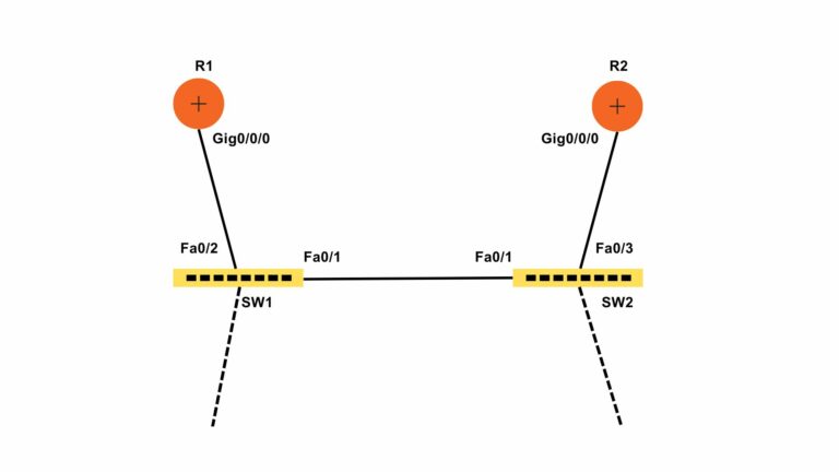
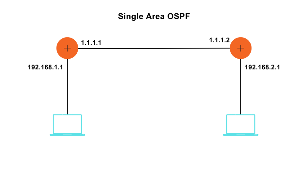
Let us understand how a Single Area OSPF is configured.
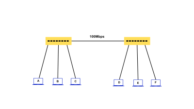
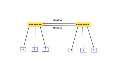
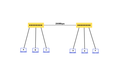
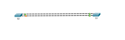
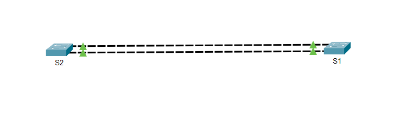
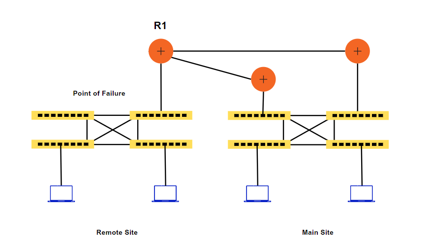
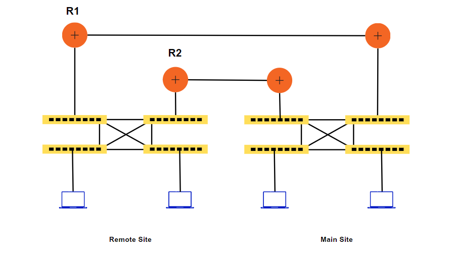
The topology is given below-
 Syntax: –
R(config)#router ospf <Process ID >
R(config-router)#network <IP Address> <Wildcard Mask> area<numerical value of the area>
R1#config t
R1(config)#router ospf 1
R1(config-router)#network 1.0.0.0 0.255.255.255 area 0
R1(config-router)#network 192.168.1.0 0.0.0.255 area 0
R2#config t
R2(config)#router ospf 1
R2(config-router)#network 1.0.0.0 0.255.255.255 area 0
R2(config-router)#network 192.168.2.0 0.0.0.255 area 0
NOTE: Here, I used 1 as the process ID and 0 as my area.
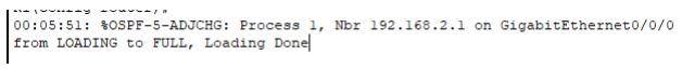
As soon as OSPF is configured on the interfaces of both routers, a message like the above pops up. They start to exchange routes with each other, and adjacency is created.
Verification: –
R1#show ip ospf neighbor
Neighbor ID Pri State Dead Time Address Interface
192.168.2.1 1 FULL/BDR 00:00:31 1.1.1.2 GigabitEthernet0/0/0
R1#show ip ospf database
OSPF Router with ID (192.168.1.1) (Process ID 1)
Router Link States (Area 0)
Link ID ADV Router Age Seq# Checksum Link count
192.168.1.1 192.168.1.1 111 0x80000003 0x007a7e 2
192.168.2.1 192.168.2.1 88 0x80000003 0x008b69 2
Net Link States (Area 0)
Link ID ADV Router Age Seq# Checksum
1.1.1.1 192.168.1.1 111 0x80000001 0x00fd37
R1#show ip route
Codes: L – local, C – connected, S – static, R – RIP, M – mobile, B – BGP
D – EIGRP, EX – EIGRP external, O – OSPF, IA – OSPF inter area
N1 – OSPF NSSA external type 1, N2 – OSPF NSSA external type 2
E1 – OSPF external type 1, E2 – OSPF external type 2, E – EGP
i – IS-IS, L1 – IS-IS level-1, L2 – IS-IS level-2, ia – IS-IS inter area
* – candidate default, U – per-user static route, o – ODR
P – periodic downloaded static route
Gateway of last resort is not set
1.0.0.0/8 is variably subnetted, 2 subnets, 2 masks
C 1.0.0.0/8 is directly connected, GigabitEthernet0/0/0
L 1.1.1.1/32 is directly connected, GigabitEthernet0/0/0
192.168.1.0/24 is variably subnetted, 2 subnets, 2 masks
C 192.168.1.0/24 is directly connected, GigabitEthernet0/0/1
L 192.168.1.1/32 is directly connected, GigabitEthernet0/0/1
O 192.168.2.0/24 [110/2] via 1.1.1.2, 00:01:38, GigabitEthernet0/0/0
R1#show ip route ospf
O 192.168.2.0 [110/2] via 1.1.1.2, 00:02:12, GigabitEthernet0/0/0
Let us verify on Router 2 as well.

R2#show ip ospf neighbor
Neighbor ID Pri State Dead Time Address Interface
192.168.1.1 1 FULL/DR 00:00:32 1.1.1.1 GigabitEthernet0/0/0
R2#show ip ospf neighbor
Neighbor ID Pri State Dead Time Address Interface
192.168.1.1 1 FULL/DR 00:00:37 1.1.1.1 GigabitEthernet0/0/0
R2#show ip route
Codes: L – local, C – connected, S – static, R – RIP, M – mobile, B – BGP
D – EIGRP, EX – EIGRP external, O – OSPF, IA – OSPF inter area
N1 – OSPF NSSA external type 1, N2 – OSPF NSSA external type 2
E1 – OSPF external type 1, E2 – OSPF external type 2, E – EGP
i – IS-IS, L1 – IS-IS level-1, L2 – IS-IS level-2, ia – IS-IS inter area
* – candidate default, U – per-user static route, o – ODR
P – periodic downloaded static route
Gateway of last resort is not set
1.0.0.0/8 is variably subnetted, 2 subnets, 2 masks
C 1.0.0.0/8 is directly connected, GigabitEthernet0/0/0
L 1.1.1.2/32 is directly connected, GigabitEthernet0/0/0
O 192.168.1.0/24 [110/2] via 1.1.1.1, 00:06:40, GigabitEthernet0/0/0
192.168.2.0/24 is variably subnetted, 2 subnets, 2 masks
C 192.168.2.0/24 is directly connected, GigabitEthernet0/0/1
L 192.168.2.1/32 is directly connected, GigabitEthernet0/0/1
R2#show ip route ospf
O 192.168.1.0 [110/2] via 1.1.1.1, 00:06:45, GigabitEthernet0/0/0
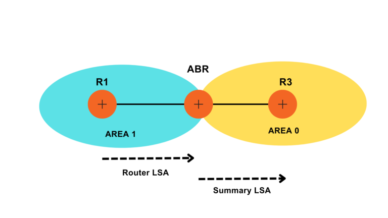
Multi Area OSPF configuration
In a multi-area OSPF configuration, the network is classified into diverse areas, each with its own set of routers. The areas are associated to a central backbone area, known as Area 0. This hierarchical structure helps to optimize network performance and scalability.
How does Multi Area OSPF get configured?
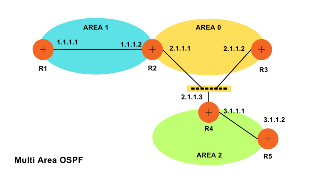
R1(config)#router ospf 1
R1(config-router)#network 1.0.0.0 0.255.255.255 area 1
R2(config)#router ospf 1
R2(config-router)#network 1.0.0.0 0.255.255.255 area 1
R2(config-router)#network 2.0.0.0 0.255.255.255 area 0
R3(config)#router ospf 1
R3(config-router)#network 2.0.0.0 0.255.255.255 area 0
R4(config)#router ospf 1
R4(config-router)#network 2.0.0.0 0.255.255.255 area 0
R4(config-router)#network 3.0.0.0 0.255.255.255 area 2
R5(config)#router ospf 1
R5(config-router)#network 3.0.0.0 0.255.255.255 area 2
Verification: –
R1#show ip ospf neighbor
Neighbor ID Pri State Dead Time Address Interface
2.1.1.1 1 FULL/DR 00:00:39 1.1.1.2 GigabitEthernet0/0/0
R1#show ip route
Codes: L – local, C – connected, S – static, R – RIP, M – mobile, B – BGP
D – EIGRP, EX – EIGRP external, O – OSPF, IA – OSPF inter area
N1 – OSPF NSSA external type 1, N2 – OSPF NSSA external type 2
E1 – OSPF external type 1, E2 – OSPF external type 2, E – EGP
i – IS-IS, L1 – IS-IS level-1, L2 – IS-IS level-2, ia – IS-IS inter area
* – candidate default, U – per-user static route, o – ODR
P – periodic downloaded static route
Gateway of last resort is not set
1.0.0.0/8 is variably subnetted, 2 subnets, 2 masks
C 1.0.0.0/8 is directly connected, GigabitEthernet0/0/0
L 1.1.1.1/32 is directly connected, GigabitEthernet0/0/0
O IA 2.0.0.0/8 [110/2] via 1.1.1.2, 00:03:42, GigabitEthernet0/0/0
O IA 3.0.0.0/8 [110/3] via 1.1.1.2, 00:02:01, GigabitEthernet0/0/0
R1#show ip route ospf
O IA 2.0.0.0 [110/2] via 1.1.1.2, 00:03:59, GigabitEthernet0/0/0
O IA 3.0.0.0 [110/3] via 1.1.1.2, 00:02:18, GigabitEthernet0/0/0
R1#show ip ospf database
OSPF Router with ID (1.1.1.1) (Process ID 1)
Router Link States (Area 1)
Link ID ADV Router Age Seq# Checksum Link count
1.1.1.1 1.1.1.1 262 0x80000002 0x00fb47 1
2.1.1.1 2.1.1.1 262 0x80000003 0x00f449 1
Net Link States (Area 1)
Link ID ADV Router Age Seq# Checksum
1.1.1.2 2.1.1.1 262 0x80000001 0x00e7eb
Summary Net Link States (Area 1)
Link ID ADV Router Age Seq# Checksum
2.0.0.0 2.1.1.1 257 0x80000001 0x005205
3.0.0.0 2.1.1.1 152 0x80000002 0x004d07
R1#show ip ospf interface
GigabitEthernet0/0/0 is up, line protocol is up
Internet address is 1.1.1.1/8, Area 1
Process ID 1, Router ID 1.1.1.1, Network Type BROADCAST, Cost: 1
Transmit Delay is 1 sec, State BDR, Priority 1
Designated Router (ID) 2.1.1.1, Interface address 1.1.1.2
Backup Designated Router (ID) 1.1.1.1, Interface address 1.1.1.1
Timer intervals configured, Hello 10, Dead 40, Wait 40, Retransmit 5
Hello due in 00:00:02
Index 1/1, flood queue length 0
Next 0x0(0)/0x0(0)
Last flood scan length is 1, maximum is 1
Last flood scan time is 0 msec, maximum is 0 msec
Neighbor Count is 1, Adjacent neighbor count is 1
Adjacent with neighbor 2.1.1.1 (Designated Router)
Suppress hello for 0 neighbor(s)
R2#show ip route
Codes: L – local, C – connected, S – static, R – RIP, M – mobile, B – BGP
D – EIGRP, EX – EIGRP external, O – OSPF, IA – OSPF inter area
N1 – OSPF NSSA external type 1, N2 – OSPF NSSA external type 2
E1 – OSPF external type 1, E2 – OSPF external type 2, E – EGP
i – IS-IS, L1 – IS-IS level-1, L2 – IS-IS level-2, ia – IS-IS inter area
* – candidate default, U – per-user static route, o – ODR
P – periodic downloaded static route
Gateway of last resort is not set
1.0.0.0/8 is variably subnetted, 2 subnets, 2 masks
C 1.0.0.0/8 is directly connected, GigabitEthernet0/0/0
L 1.1.1.2/32 is directly connected, GigabitEthernet0/0/0
2.0.0.0/8 is variably subnetted, 2 subnets, 2 masks
C 2.0.0.0/8 is directly connected, GigabitEthernet0/0/1
L 2.1.1.1/32 is directly connected, GigabitEthernet0/0/1
O IA 3.0.0.0/8 [110/2] via 2.1.1.3, 00:06:51, GigabitEthernet0/0/1
R2#show ip ospf neighbor
Neighbor ID Pri State Dead Time Address Interface
1.1.1.1 1 FULL/BDR 00:00:39 1.1.1.1 GigabitEthernet0/0/0
2.1.1.2 1 FULL/BDR 00:00:37 2.1.1.2 GigabitEthernet0/0/1
3.1.1.1 1 FULL/DROTHER 00:00:35 2.1.1.3 GigabitEthernet0/0/1
R2#show ip ospf database
OSPF Router with ID (2.1.1.1) (Process ID 1)
Router Link States (Area 0)
Link ID ADV Router Age Seq# Checksum Link count
2.1.1.1 2.1.1.1 524 0x80000002 0x00f04e 1
2.1.1.2 2.1.1.2 524 0x80000002 0x00eb51 1
3.1.1.1 3.1.1.1 446 0x80000003 0x00f445 1
Net Link States (Area 0)
Link ID ADV Router Age Seq# Checksum
2.1.1.1 2.1.1.1 464 0x80000002 0x00dc31
Summary Net Link States (Area 0)
Link ID ADV Router Age Seq# Checksum
1.0.0.0 2.1.1.1 536 0x80000001 0x005ff8
3.0.0.0 3.1.1.1 436 0x80000001 0x003c19
 Router Link States (Area 1)
Link ID ADV Router Age Seq# Checksum Link count
2.1.1.1 2.1.1.1 541 0x80000003 0x00f449 1
1.1.1.1 1.1.1.1 541 0x80000002 0x00fb47 1
Net Link States (Area 1)
Link ID ADV Router Age Seq# Checksum
1.1.1.2 2.1.1.1 541 0x80000001 0x00e7eb
Summary Net Link States (Area 1)
Link ID ADV Router Age Seq# Checksum
2.0.0.0 2.1.1.1 536 0x80000001 0x005205
3.0.0.0 2.1.1.1 431 0x80000002 0x004d07
R2#show ip ospf interface
GigabitEthernet0/0/1 is up, line protocol is up
Internet address is 2.1.1.1/8, Area 0
Process ID 1, Router ID 2.1.1.1, Network Type BROADCAST, Cost: 1
Transmit Delay is 1 sec, State DR, Priority 1
Designated Router (ID) 2.1.1.1, Interface address 2.1.1.1
Backup Designated Router (ID) 2.1.1.2, Interface address 2.1.1.2
Timer intervals configured, Hello 10, Dead 40, Wait 40, Retransmit 5
Hello due in 00:00:08
Index 1/1, flood queue length 0
Next 0x0(0)/0x0(0)
Last flood scan length is 1, maximum is 1
Last flood scan time is 0 msec, maximum is 0 msec
Neighbor Count is 2, Adjacent neighbor count is 2
Adjacent with neighbor 2.1.1.2 (Backup Designated Router)
Adjacent with neighbor 3.1.1.1
Suppress hello for 0 neighbor(s)
GigabitEthernet0/0/0 is up, line protocol is up
Internet address is 1.1.1.2/8, Area 1
Process ID 1, Router ID 2.1.1.1, Network Type BROADCAST, Cost: 1
Transmit Delay is 1 sec, State DR, Priority 1
Designated Router (ID) 2.1.1.1, Interface address 1.1.1.2
Backup Designated Router (ID) 1.1.1.1, Interface address 1.1.1.1
Timer intervals configured, Hello 10, Dead 40, Wait 40, Retransmit 5
Hello due in 00:00:05
Index 2/2, flood queue length 0
Next 0x0(0)/0x0(0)
Last flood scan length is 1, maximum is 1
Last flood scan time is 0 msec, maximum is 0 msec
Neighbor Count is 1, Adjacent neighbor count is 1
Adjacent with neighbor 1.1.1.1 (Backup Designated Router)
Suppress hello for 0 neighbor(s)