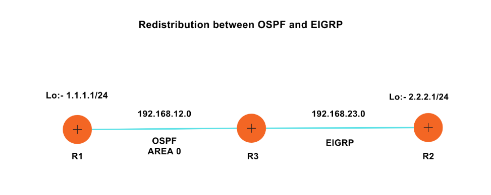
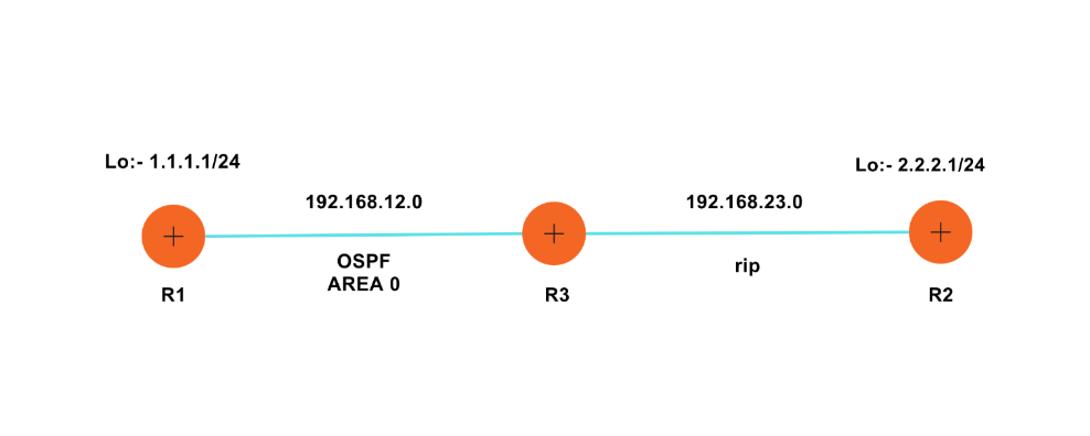
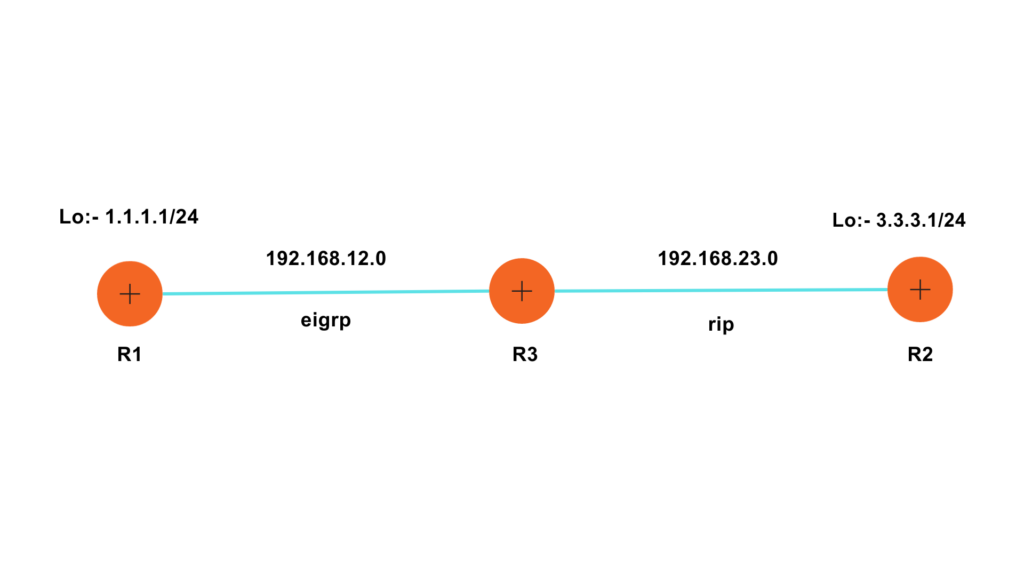
Configuring Routing Protocols:-
R1:-
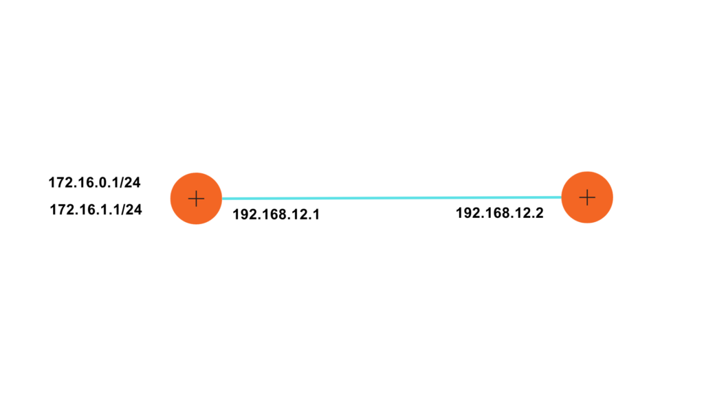
R1(config)#interface GigabitEthernet0/0/0
R1(config-if)#ip address 192.168.12.1
R1(config-if)#ip address 192.168.12.1 255.255.255.0
R1(config-if)#no shutdown
R1(config-if)#exit
R1(config)#interface loopback 1
R1(config-if)#ip address 1.1.1.1 255.255.255.0
R1(config-if)#exit
R1(config)#router eigrp 1
R1(config-router)#no auto-summary
R1(config-router)#network 192.168.12.0
R1(config-router)#network 1.1.1.0
R2:-
R2(config)#interface GigabitEthernet0/0/0
R2(config-if)#ip address 192.168.23.1 255.255.255.0
R2(config-if)#no shutdown
R2(config-if)#exit
R2(config)#interface loopback 1
R2(config-if)#ip address 2.2.2.1 255.255.255.0
R2(config)#router rip
R2(config-router)#version 2
R2(config-router)#no auto-summary
R2(config-router)#network 192.168.23.0
R2(config-router)#network 2.2.2.0
R2(config-router)#exit
R3: –
Router(config)#hostname R3
R3(config)#interface GigabitEthernet0/0/0
R3(config-if)#ip address 192.168.12.2 255.255.255.0
R3(config-if)#no shutdown
R3(config)#interface GigabitEthernet0/0/1
R3(config-if)#ip add
R3(config-if)#ip address 192.168.23.2 255.255.255.0
R3(config-if)#no shutdown
R3(config)#interface lo
R3(config)#interface loopback 1
R3(config-router)#router eigrp 1
R3(config-router)#no auto-summary
R3(config-router)#network 192.168.12.0
R3(config-router)#exit
R3(config-router)#version 2
R3(config-router)#no auto-summary
R3(config-router)#network 192.168.23.0
Verification: –
R1#show ip route
Codes: L – local, C – connected, S – static, R – RIP, M – mobile, B – BGP
D – EIGRP, EX – EIGRP external, O – OSPF, IA – OSPF inter area
N1 – OSPF NSSA external type 1, N2 – OSPF NSSA external type 2
E1 – OSPF external type 1, E2 – OSPF external type 2, E – EGP
i – IS-IS, L1 – IS-IS level-1, L2 – IS-IS level-2, ia – IS-IS inter area
* – candidate default, U – per-user static route, o – ODR
P – periodic downloaded static route
The Gateway of last resort is not set
1.0.0.0/8 is variably subnetted, 2 subnets, 2 masks
C 1.1.1.0/24 is directly connected, Loopback1
L 1.1.1.1/32 is directly connected, Loopback1
192.168.12.0/24 is variably subnetted, 2 subnets, 2 masks
C 192.168.12.0/24 is directly connected, GigabitEthernet0/0/0
L 192.168.12.1/32 is directly connected, GigabitEthernet0/0/0
R2#show ip route
Codes: L – local, C – connected, S – static, R – RIP, M – mobile, B – BGP
D – EIGRP, EX – EIGRP external, O – OSPF, IA – OSPF inter area
N1 – OSPF NSSA external type 1, N2 – OSPF NSSA external type 2
E1 – OSPF external type 1, E2 – OSPF external type 2, E – EGP
i – IS-IS, L1 – IS-IS level-1, L2 – IS-IS level-2, ia – IS-IS inter area
* – candidate default, U – per-user static route, o – ODR
P – periodic downloaded static route
The Gateway of last resort is not set
2.0.0.0/8 is variably subnetted, 2 subnets, 2 masks
C 2.2.2.0/24 is directly connected, Loopback1
L 2.2.2.1/32 is directly connected, Loopback1
192.168.23.0/24 is variably subnetted, 2 subnets, 2 masks
C 192.168.23.0/24 is directly connected, GigabitEthernet0/0/0
L 192.168.23.1/32 is directly connected, GigabitEthernet0/0/0
R3>show ip route
Codes: L – local, C – connected, S – static, R – RIP, M – mobile, B – BGP
D – EIGRP, EX – EIGRP external, O – OSPF, IA – OSPF inter area
N1 – OSPF NSSA external type 1, N2 – OSPF NSSA external type 2
E1 – OSPF external type 1, E2 – OSPF external type 2, E – EGP
i – IS-IS, L1 – IS-IS level-1, L2 – IS-IS level-2, ia – IS-IS inter area
* – candidate default, U – per-user static route, o – ODR
P – periodic downloaded static route
The Gateway of last resort is not set
1.0.0.0/24 is subnetted, 1 subnets
D 1.1.1.0/24 [90/130816] via 192.168.12.1, 00:11:17, GigabitEthernet0/0/0
2.0.0.0/24 is subnetted, 1 subnets
R 2.2.2.0/24 [120/1] via 192.168.23.1, 00:00:22, GigabitEthernet0/0/1
192.168.12.0/24 is variably subnetted, 2 subnets, 2 masks
C 192.168.12.0/24 is directly connected, GigabitEthernet0/0/0
L 192.168.12.2/32 is directly connected, GigabitEthernet0/0/0
192.168.23.0/24 is variably subnetted, 2 subnets, 2 masks
C 192.168.23.0/24 is directly connected, GigabitEthernet0/0/1
L 192.168.23.2/32 is directly connected, GigabitEthernet0/0/1
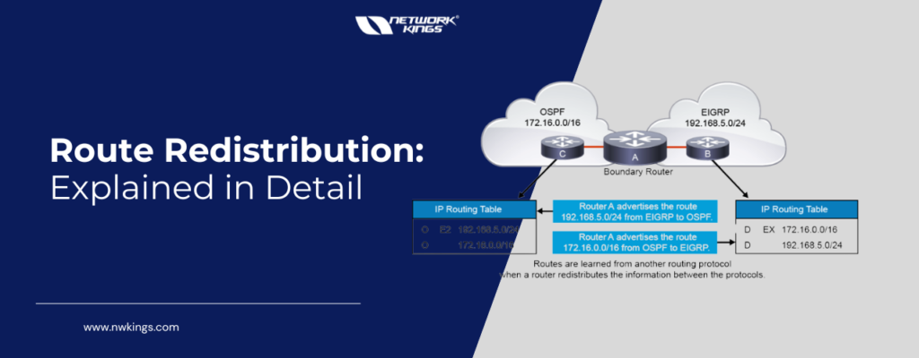
Redistribution: –
R3(config)#router rip
R3(config-router)#redistribute eigrp 1
R3(config-router)#redistribute eigrp 1 ?
metric Metric for redistributed routes
R3(config-router)#redistribute eigrp 1 metric 5
R3(config-router)#exit
R3(config)#router eigrp 1
R3(config-router)#redistribute rip metric ?
(We can configure different metrics in it)
<1-4294967295> Bandwidth metric in Kbits per second
R3(config-router)#redistribute rip metric 1000 ?
<0-4294967295> EIGRP delay metric, in 10 microsecond units
R3(config-router)#redistribute rip metric 1000 100 ?
<0-255> EIGRP reliability metric where 255 is 100% reliable
R3(config-router)#redistribute rip metric 1000 100 255 ?
<1-255> EIGRP Effective bandwidth metric (Loading) where 255 is 100% loaded
R3(config-router)#redistribute rip metric 1000 100 255 1 ?
<1-65535> EIGRP MTU of the path
R3(config-router)#redistribute rip metric 1000 100 255 1 1500
R3(config-router)#exit
Verification: –
We can now see redistributed routes also.
R3#show ip route
Codes: L – local, C – connected, S – static, R – RIP, M – mobile, B – BGP
D – EIGRP, EX – EIGRP external, O – OSPF, IA – OSPF inter area
N1 – OSPF NSSA external type 1, N2 – OSPF NSSA external type 2
E1 – OSPF external type 1, E2 – OSPF external type 2, E – EGP
i – IS-IS, L1 – IS-IS level-1, L2 – IS-IS level-2, ia – IS-IS inter area
* – candidate default, U – per-user static route, o – ODR
P – periodic downloaded static route
The Gateway of last resort is not set
D 1.0.0.0/8 [90/130816] via 192.168.12.1, 00:15:55, GigabitEthernet0/0/0
2.0.0.0/24 is subnetted, 1 subnets
R 2.2.2.0/24 [120/1] via 192.168.23.1, 00:00:04, GigabitEthernet0/0/1
192.168.12.0/24 is variably subnetted, 2 subnets, 2 masks
C 192.168.12.0/24 is directly connected, GigabitEthernet0/0/0
L 192.168.12.2/32 is directly connected, GigabitEthernet0/0/0
192.168.23.0/24 is variably subnetted, 2 subnets, 2 masks
C 192.168.23.0/24 is directly connected, GigabitEthernet0/0/1
L 192.168.23.2/32 is directly connected, GigabitEthernet0/0/1
R1>show ip route
Codes: L – local, C – connected, S – static, R – RIP, M – mobile, B – BGP
D – EIGRP, EX – EIGRP external, O – OSPF, IA – OSPF inter area
N1 – OSPF NSSA external type 1, N2 – OSPF NSSA external type 2
E1 – OSPF external type 1, E2 – OSPF external type 2, E – EGP
i – IS-IS, L1 – IS-IS level-1, L2 – IS-IS level-2, ia – IS-IS inter area
* – candidate default, U – per-user static route, o – ODR
P – periodic downloaded static route
The Gateway of last resort is not set
1.0.0.0/8 is variably subnetted, 3 subnets, 3 masks
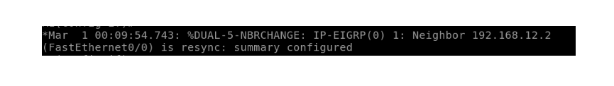
D 1.0.0.0/8 is a summary, 00:16:17, Null0
C 1.1.1.0/24 is directly connected, Loopback1
L 1.1.1.1/32 is directly connected, Loopback1
2.0.0.0/24 is subnetted, 1 subnets
D EX 2.2.2.0/24 [170/2585856] via 192.168.12.2, 00:00:55, GigabitEthernet0/0/0
192.168.12.0/24 is variably subnetted, 2 subnets, 2 masks
C 192.168.12.0/24 is directly connected, GigabitEthernet0/0/0
L 192.168.12.1/32 is directly connected, GigabitEthernet0/0/0
D EX 192.168.23.0/24 [170/2585856] via 192.168.12.2, 00:00:55, GigabitEthernet0/0/0
R2>show ip route
Codes: L – local, C – connected, S – static, R – RIP, M – mobile, B – BGP
D – EIGRP, EX – EIGRP external, O – OSPF, IA – OSPF inter area
N1 – OSPF NSSA external type 1, N2 – OSPF NSSA external type 2
E1 – OSPF external type 1, E2 – OSPF external type 2, E – EGP
i – IS-IS, L1 – IS-IS level-1, L2 – IS-IS level-2, ia – IS-IS inter area
* – candidate default, U – per-user static route, o – ODR
P – periodic downloaded static route
The Gateway of last resort is not set
R 1.0.0.0/8 [120/5] via 192.168.23.2, 00:00:08, GigabitEthernet0/0/0
2.0.0.0/8 is variably subnetted, 2 subnets, 2 masks
C 2.2.2.0/24 is directly connected, Loopback1
L 2.2.2.1/32 is directly connected, Loopback1
R 192.168.12.0/24 [120/5] via 192.168.23.2, 00:00:08, GigabitEthernet0/0/0
192.168.23.0/24 is variably subnetted, 2 subnets, 2 masks
C 192.168.23.0/24 is directly connected, GigabitEthernet0/0/0
L 192.168.23.1/32 is directly connected, GigabitEthernet0/0/0


 C 1.0.0.0/8 is directly connected, GigabitEthernet0/0/0