Network Kings

LIMITED TIME OFFER

$999 $499 only For All Access Pass Today! USE PROMO CODE : LIMITED

d :
h :
m

Router on a Stick: Explained

router on a stick configuration

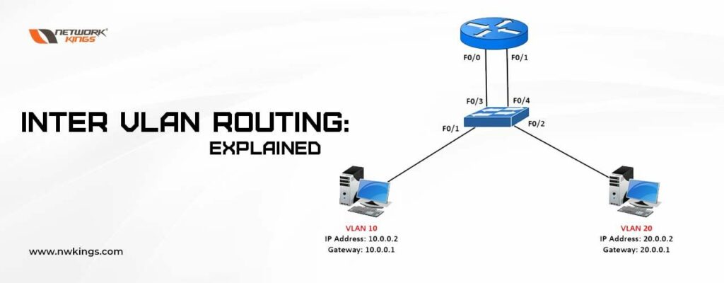
VLANs divide traffic in a LAN according to the needs and increase the broadcast domain. There are methods using which two different Vans can communicate with each other. This process is known as Inter-VLAN routing.

We have discussed Inter-VLAN routing and different methods that can be used to make different VLANs communicate with each other. Let us now see the configuration of one of the popular methods of Inter-VLAN routing, i.e., Router on a stick.

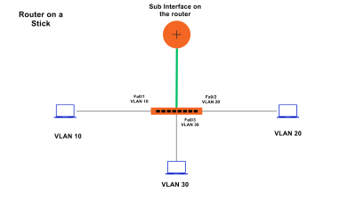
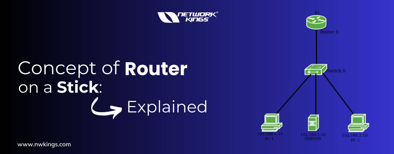
What is Router on a Stick?

Router on a stick or ROAS is a method in which we learn to create a sub-interface on the router and use VLAN tagging to differentiate between the traffic. Let us see how this can be attained.

Router on a Stick Configuration:-

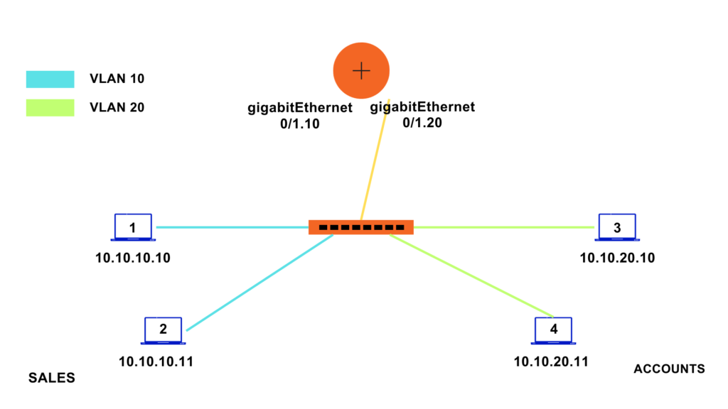
Let us take a simple topology with VLAN 10 and VLAN 20.
VLAN 10 is used for sales and VLAN 20 is used for accounts.
PC 1 and 2 are connected to the port in VLAN 10 and are configured with IP 10.10.10.10 and 10.10.10.11
PC 3 and PC 4 are connected to the port in VLAN 20 and are configured with IP 10.10.20.10 and 10.10.20.11

router on a stick configuration

Configuration on Switch:-

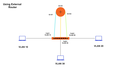
Interface FastEthernet 0/2 and fastEthernet 0/3 are in VLAN 10 while interface FastEthernet 0/4 and FastEthernet 0/5 are assigned to VLAN 20.
Interface FastEthernet 0/1 of the switch should be configured as a trunk because all the VLAN passes to the router from this link only.

S1#configure terminal  

S1(config)#vlan 10 

S1(config-vlan)#name sales 

S1(config-vlan)#exit 

S1(config)#vlan 20 

S1(config-vlan)#name accounts 

S1(config-vlan)#exit 


S1(config)#interface range fastEthernet 0/2 – 3 

S1(config-if-range)#switchport mode access  

S1(config-if-range)#switchport access vlan 10 

S1(config-if-range)#exit 


S1(config)#interface range fastEthernet 0/4 – 5 

S1(config-if-range)#switchport mode access  

S1(config-if-range)#switchport access vlan 20 

S1(config-if-range)#exit 


S1(config)#interface fastEthernet 0/1 

S1(config-if)#switchport mode trunk 

Configuration on Router:-

R1(config)#interface GigabitEthernet0/1 

R1(config-if)#no ip address  

(We will configure different IP addresses on different sub-interfaces)

R1(config-if)#no shutdown  


R1(config-if)#exit 

R1(config)#interface gigabitEthernet 0/1.10 

%LINK-5-CHANGED: Interface GigabitEthernet0/1.10, changed state to up

Sub interface comes up, no need to give a shutdown command here since the actual physical interface i.e. GigabitEthernet0/1 is already up. 


R1(config-subif)#encapsulation dot1Q 10 


Tagging VLAN 10 to router sub-interface so that routers know which subinterface the traffic belongs to whenever traffic with VLAN 10 comes. Also, whenever traffic leaves the 1.10 subinterface a VLAN 10 will be assigned to it. 


R1(config-subif)#ip address 10.10.10.1 255.255.255.0 

R1(config-subif)#exit 


Similarly, let us create a subinterface for VLAN 20 


R1(config)#interface gigabitEthernet 0/1.20 


R1(config-subif)#ip address 10.10.20.1 255.255.255.0 


Configuring IP routing on a LAN subinterface is only allowed if that 

subinterface is already configured as part of an IEEE 802.10, IEEE 802.1Q, 

or ISL vLAN. 


If we assign an IP address before the encapsulation, this error message will pop up. 


R1(config-subif)# encapsulation dot1Q 20 

R1(config-subif)#ip address 10.10.20.1 255.255.255.0 


R1>show ip route  


Codes: L – local, C – connected, S – static, R – RIP, M – mobile, B – BGP 

D – EIGRP, EX – EIGRP external, O – OSPF, IA – OSPF inter area 

N1 – OSPF NSSA external type 1, N2 – OSPF NSSA external type 2 

E1 – OSPF external type 1, E2 – OSPF external type 2, E – EGP 

i – IS-IS, L1 – IS-IS level-1, L2 – IS-IS level-2, ia – IS-IS inter area 

* – candidate default, U – per-user static route, o – ODR 

P – periodic downloaded static route 


The Gateway of last resort is not set

10.0.0.0/8 is variably subnetted, 4 subnets, 2 masks 

C 10.10.10.0/24 is directly connected, GigabitEthernet0/1.10 

L 10.10.10.1/32 is directly connected, GigabitEthernet0/1.10 

C 10.10.20.0/24 is directly connected, GigabitEthernet0/1.20 

L 10.10.20.1/32 is directly connected, GigabitEthernet0/1.20 

Let us verify and try to ping a PC in VLAN 20 from a PC configured with VLAN 10.

C:\>ping 10.10.20.10 


Pinging 10.10.20.10 with 32 bytes of data: 


Reply from 10.10.20.10: bytes=32 time<1ms TTL=127 

Reply from 10.10.20.10: bytes=32 time<1ms TTL=127 

Reply from 10.10.20.10: bytes=32 time<1ms TTL=127 

Reply from 10.10.20.10: bytes=32 time=11ms TTL=127 


Ping statistics for 10.10.20.10: 

Packets: Sent = 4, Received = 4, Lost = 0 (0% loss), 

Approximate round trip times in milli-seconds: 

Minimum = 0ms, Maximum = 11ms, Average = 2ms 

router on a stick configuration

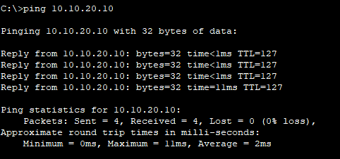
See two different VLANs are now allowed to communicate with each other.

Inter VLAN Routing: Explained

inter vlan routing
inter vlan routing

Before talking about Inter VLAN routing, let me give you a brief introduction to VLAN first.

VLAN is a logical grouping of network devices connected to a switch. VLANs are used to create smaller broadcast domains at layer 2 by assigning different ports to different subnetworks on the same switch so that two or more departments cannot communicate with each other which helps to reduce unnecessary traffic in a network. Also, the use of VLAN in an organization is a common practice. This allows different departments to remain isolated from each other and saves bandwidth.

But what if two different VLANs or we can say two different departments of an organization want to communicate with each other? Can this be made possible?

What is Inter VLAN routing?

Inter VLAN routing is the process of enabling communication between devices on different VLANs within the same network. Without inter VLAN routing, devices on separate VLANs are essentially isolated from each other, unable to exchange data or access resources. Inter VLAN routing helps to resolve this communication gap by allowing data to flow between VLANs. To allow communication between different VLANs we take the help of routing and hence we need a device that can perform routing i.e., router or layer 3 switches.

Why is Inter-VLAN routing used?

As we discussed Inter VLAN routing can help to build a communication channel between two or more different VLANs, but besides this, it also has some other uses: –

  • Security

VLANs are used to enhance security by keeping sensitive data on a separate VLAN and ensuring that no unauthorized devices can access it. Inter-VLAN helps authorized devices access these resources and data. 

  • Shared Resources

Inter VLAN routing allows devices on different VLANs to share network resources efficiently. For instance, printers, file servers, and network-attached storage (NAS) devices can be placed on a separate VLAN; users from multiple VLANs can access these shared resources. This simplifies resource management and utilization. 

  • Scaling and Growth

As an organization grows, the network grows and new services are added, inter VLAN routing can help maintain efficient communication between VLANs without physically reconfiguring the network. 

  • Traffic Management and Optimization

By routing traffic between VLANs, you have control over how traffic flows within your network. This allows you to optimize network performance and ensure that bandwidth is allocated according to the organization’s needs and policies. 

How does Inter-VLAN routing work?

Inter VLAN routing can be implemented using three methods, namely- 

  • External Router

The oldest method of implementing Inter VLAN routing is using a router with multiple interfaces and each router interface is connected to ports on a switch configured with different VLAN. The router interface acts as a default gateway for the particular VLAN. 

An example of this method is shown in the diagram below. 

Ports on the switch are assigned to particular VLANs as mentioned and each port is connected to the port on the RE. When a PC in VLAN 10 wants to communicate with a PC configured at VLAN 20, the packet is forwarded to the default gateway of VLAN 10 i.e., Gi0/0. The router examines the destination address and sends out a packet to the Gi0/1 interface. A packet that travels to the fa0/2 port of the switch and finally reaches PC 2 i.e., PC configured with VLAN 20. 

External Router

This method is effective but it has a drawback. Since each VLAN requires a different default gateway and hence different RE ports. It becomes a costly method. RE used to have a smaller number of ports. In our example, we had only three VLANs. What is an organization that has 10 different departments and requires 10 different VLANs?  

Hence this solution is not scalable. 

  • Router-on-a-Stick

As we saw in the case of the old Inter-Vlan routing method we require ports equal to the number of VLAN configured in a network but the router-on-the-stick method overcomes this drawback. 

NOTE: In the case of the Router-on-a-stick method we only require one physical Ethernet interface. 

But, how is it possible to enable it using a single port?

The router uses the concept of Sub-Interfaces, each associated with a specific VLAN. These Sub-Interfaces are assigned IP addresses, acting as the default gateways for devices in their respective VLANs. VLAN tagging (usually with 802.1Q) is employed to differentiate traffic from different VLANs as it passes through the single physical connection to the router. This router port is connected to the layer 2 switch trunk port.

When a packet tagged with a VLAN enters the router sub-interface, the router makes the routing decision based on the destination IP Address and then it determines the exit interface for that particular packet. Since the exit sub-interface is also configured as an 802.1Q sub-interface, the new VLAN is tagged at the data frames and forwarded accordingly.

Router-on-a-Stick

This method is cost-effective since it requires only one physical router. However, it can also become a bottleneck if there is a significant amount of inter-VLAN traffic since all the traffic must pass through a single physical interface. Since it employs the use of a single physical interface, latency is also high. Also, if this physical interface goes down for any reason, an outage in a network can occur. 

  • Switch Virtual Interface/ Use of Layer 3 Switch

A Layer 3 switch, also known as a multilayer switch, combines the features of a traditional network switch and a router. A layer 3 switch is also known as a multi-layer switch since it can operate on both layer 2 and layer 3. We can configure a switched virtual interface on a layer 3 switch.  

it has VLAN interfaces configured for each VLAN and can route traffic between these VLANs using the physical interfaces connected to the switch. 

Devices within each VLAN use the Layer 3 switch as their default gateway. DVI performs the same function for the VLAN as a router sub-interface does but it is much faster than it since it employs the same hardware for routing and switching. This method is also not limited to one link because the concept of EtherChannel can also be used between switches to increase the bandwidth. Latency is also lower in SVI. 

SVI

This approach is efficient and provides high-speed inter VLAN routing because it eliminates the need for a separate physical router. The main disadvantage of using this method is the cost. Generally, Multi-Layer switches are expensive devices.

Also, the configuration for Multi-Layer switches is a little complex.

What is EIGRP in Networking? Explained

eigrp in networking
eigrp in networking

EIGRP in networking, also called Enhance Interior Gateway Routing Protocol (EIGRP), works on layer 3 of the OSI model and helps find the best path. It is an updated version of the IGRP protocol. EIGRP used to be a Cisco Proprietary protocol but it became an Open standard protocol and can be configured on devices other than Cisco. Administrative distance for EIGRP is 90 for internal routes and 170 for external routes. EIGRP uses protocol number 88.

EIGRP in networking is an advanced distance vector routing protocol, also called hybrid routing protocol, that uses the properties of Distance vector routing protocol as well as link-state routing protocol.

In the Enhanced Interior Gateway Routing Protocol (EIGRP), multicasting efficiently exchanges routing information between routers within the same Autonomous System (AS). EIGRP uses a specific multicast address for this purpose. The multicast address used by EIGRP for IPv4 is 224.0.0.10. In the case of IPv6, EIGRP uses the multicast address FF02::A.

EIGRP routers send their routing updates and queries to this multicast address, allowing other routers in the same EIGRP AS to receive and process the routing information. Multicasting helps reduce unnecessary network traffic by ensuring that EIGRP updates are only sent to routers interested in receiving them, which is especially important in larger networks.

What are the features of EIGRP in Networking?

The features of EIGRP in Networking are as follows- 

  • EIGRP uses a Diffusion Update Algorithm (DUAL). This algorithm helps EIGRP routers to perform rapid convergence when changes occur in the network. EIGRP also sends updates when there is a change in the network topology, unlike traditional distance routing protocol that sends updates periodically. This helps EIRGRP become efficient and saves bandwidth. 
  • EIGRP supports Variable Length Subnet Mask (VLSM) and Classless Inter-Domain Routing (CIDR) which allows efficient use of IP Address. 
  • EIGRP supports route summarization which helps to reduce the size of the routing table and minimize the amount of routing information exchanged between routers. 
  • EIGRP uses loop prevention mechanisms such as the split horizon to prevent routing loops in the network. 

What are the types of EIGRP Packets?

Enhanced Interior Gateway Routing Protocol (EIGRP) different types of packets to facilitate the exchange of routing information and maintain neighbour relationships between routers within the same Autonomous System (AS).

  • Hello Packet

This packet is used for neighbour discovery and to maintain the neighbourship after it is established. These packets are sent by EIGRP routers periodically. When 2 routers receive the EIGRP Hello Packet, they become neighbours. 

  • Update Packets

These packets are used to update neighboring routers about the changes in the network topology. These packets are only sent when there is a change in network topology like route deletion, new routes addition, link failure, metric update, etc. 

  • Query packet

Query packets are used to request more specific information about a particular route. When a router detects a topology change and updates its routing table, it may send Query packets to its neighbors to ask for more details about routes that have become unreachable. This helps in resolving potential routing inconsistencies. 

  • Reply Packets

Reply packets are sent in response to Query packets. When a router receives a Query for specific routing information, it responds with a Reply packet, providing the requested details about the route. 

  • Acknowledgment (ACK) Packets

Acknowledgment packets are used to confirm the receipt of Update, Query, and Reply packets. When a router receives one of these packets from a neighbor, it sends back an ACK to acknowledge receipt. This helps ensure that the packets are delivered successfully. 

  • RTP (Reliable Transport Protocol) Packets

EIGRP uses RTP as its transport protocol to provide reliable and ordered delivery of packets. RTP encapsulates EIGRP Hello, Update, Query, Reply, and ACK packets for transmission between routers. It ensures that packets are delivered without duplication, loss, or out-of-order delivery.

What are EIRGP tables?

EIGRP uses some tables to maintain routing information, find the best path, and recalculate the paths when the primary path goes down for some reason. The tables used by EIGRP are:- 

  • Neighbour Table

The EIGRP Neighbour Table, keeps information on neighbouring routers with which the local router has formed EIGRP neighbour relationships. It contains information about the IP addresses of neighbours, their interface, hold timers and other parameters required for neighborship maintenance. 

The command used to see neighbor table: –  R#show ip eigrp neighbors 

  • Topology Table

It keeps detailed information about routes learned from EIGRP neighbours. This table contains entries for all known routes, including feasible successors and any potential backup routes. It includes information such as the destination network, metrics, and the state of the route (active, passive, or stuck in active). It basically includes the information of the whole topology configured within the EIGRP Autonomous System (AS). 

The command used to see the topology table: – R#show ip eigrp topology  

  • Routing Table

The Routing Table also called the global routing table contains the best routes to reach various network destinations within the EIGRP Autonomous System (AS). This table is derived from the Topology Table and is used for making forwarding decisions. EIGRP selects the routes with the lowest composite metric values to populate the Routing Table.

Basic EIGRP Configuration 


Syntax: – 


R(config)#router eigrp <Process ID> 

R(config-router)#network <Network IP> 

R(config-router)#no auto-summary :- Used to disable auto summarization of routes. 


Let us look at the below given topology: – 

routing table

R1(config)#router eigrp 1
R1(config-router)#network 192.168.13.0
R1(config-router)#no auto-summary

R2(config)#router eigrp 1
R2(config-router)#network 192.168.13.0
R2(config-router)#network 192.168.34.0
R2(config-router)#no auto-summary

R3(config)#router eigrp 1
R3(config-router)#network 192.168.34.0
R3(config-router)#no auto-summary

Verification: – 


R1#show ip eigrp topology  


IP-EIGRP Topology Table for AS 1/ID(192.168.13.1) 

Codes: P – Passive, A – Active, U – Update, Q – Query, R – Reply, 

r – Reply status 


P 192.168.13.0/24, 1 successors, FD is 2816 

via Connected, GigabitEthernet0/0/0 

P 192.168.34.0/24, 1 successors, FD is 2816 

via Connected, GigabitEthernet0/0/1 


R2#show ip route  


Codes: L – local, C – connected, S – static, R – RIP, M – mobile, B – BGP 

D – EIGRP, EX – EIGRP external, O – OSPF, IA – OSPF inter area 

N1 – OSPF NSSA external type 1, N2 – OSPF NSSA external type 2 

E1 – OSPF external type 1, E2 – OSPF external type 2, E – EGP 

i – IS-IS, L1 – IS-IS level-1, L2 – IS-IS level-2, ia – IS-IS inter area 

* – candidate default, U – per-user static route, o – ODR 

P – periodic downloaded static route 


Gateway of last resort is not set 


192.168.13.0/24 is variably subnetted, 2 subnets, 2 masks 

C 192.168.13.0/24 is directly connected, GigabitEthernet0/0/0 

L 192.168.13.2/32 is directly connected, GigabitEthernet0/0/0 

192.168.34.0/24 is variably subnetted, 2 subnets, 2 masks 

C 192.168.34.0/24 is directly connected, GigabitEthernet0/0/1 

L 192.168.34.1/32 is directly connected, GigabitEthernet0/0/1 

What do you mean by IPsec? – Explained

what is ipsec?
what is ipsec?

IPsec is a set of protocols and technologies designed to secure internet communication. It is also known as Internet protocol security. IPsec is useful in providing security and authentication to the data sent over the internet.

IP packets when sent, do not have any added security to them, and an attacker can easily access the data contained in the IP Packet.

How to secure data using IPsec?

With the help of IPsec, we can secure the data in the following ways: – 

  • Encryption

IPsec encrypts the data, so it becomes unreadable to anyone without the proper decryption key. Hence, it is only readable by the sender and receiver. This makes it difficult for cybercriminals to intercept the data. 

  • Authentication

IPsec also employs authentication mechanisms to confirm the identities of the communicating parties. It ensures that the data is transmitted between the authenticated sender and receiver, which helps to avoid man-in-the-middle attacks. 

  • Security Associations

IPsec establishes security associations (SAs) between two communicating devices. These SAs define the rules and parameters for secure communication, such as the encryption and authentication methods to be used. 

  • Tunnelling

IPsec can create a secure tunnel, known as a VPN (Virtual Private Network), between two devices or networks. This tunnel encapsulates the data, adding an extra layer of security. 

What is IKE?

IKE, also known as Internet Key Exchange, is a protocol used in IPsec which helps establish a secure communication tunnel between devices. It is responsible for exchanging the necessary cryptographic keys and security parameters required for tunnel creation and establishing secure communications.

It helps in negotiating between both parties to agree on how to secure the communication and enables the creation of security associations (SAs) for encrypted and authenticated communications.

How many IKE phases are there?

IKE has two phases, namely:-  

  • IKE Phase 1 

The primary goal of Phase 1 is to establish a secure and authenticated channel for further negotiation. This phase focuses on setting up a secure initial connection between the sender and receiver. Phase 1 is used to create a secure tunnel which we can use in Phase 2. 

  • IKE Phase 2

Phase 2 builds upon the secure channel established in Phase 1 and focuses on negotiating the parameters and keys for securing the actual data traffic. 

What functions does IKE Phase 1 perform?

The following functions are performed in IKE Phase 1: –  

  • Authentication

The parties authenticate each other’s identities using methods like pre-shared keys (PSK), digital certificates, or other authentication mechanisms. 

  • Encryption

Phase 1 can involve the use of encryption to protect the negotiation process itself. 

  • Diffie-Hellman Key Exchange

A secure method for the sender and receiver to agree on shared secret keys is established through the Diffie-Hellman key exchange. 

  • Lifetime and Refreshing

Phase 1 also defines parameters like the lifetime of the negotiation and methods for refreshing keys. 

When Phase 1 is completed, both parties have established a secure communication channel and have derived a shared secret key, known as the IKE Phase 1 key. This key is used in Phase 2 to secure the actual data traffic. 

What functions does IKE Phase 2 perform?

The following functions are performed in IKE Phase 2: –  

  • Selection of Security Policies

The sender and receiver negotiate the specific security policies, including encryption and authentication algorithms, to be used for data traffic. Either AH or ESP IPsec protocol can be used. 

  • Creation of Security Associations (SAs)

One or more SAs are created for each unique combination of source and destination, defining how data should be protected. 

  • Encapsulation Mode

In phase 2, the encapsulation mode is negotiated. The mode can either be tunnel mode or transport mode.  

When Phase 2 is completed, the devices or networks involved have established one or more SAs that define how data will be encrypted, authenticated, and transmitted between them. These SAs govern the secure communication for data packets. 

phase 1 tunnel

Internet Key Exchange is useful to make a secure tunnel but does not encrypt or authenticate the data.  

For this purpose, we use the following two protocols: – 

  • Authentication Header (AH)

AH is a protocol within IPsec that provides data integrity, authentication, and anti-replay protection for IP packets. It does not provide encryption but ensures that the data has not been tampered with during transmission. 

  • Encapsulating Security Payload (ESP)

ESP is another IPsec protocol that provides encryption, data integrity, and optional authentication. It encrypts the entire IP packet, including the payload (data), making it secure. ESP is often used in combination with AH or alone to provide encryption and authentication. 

Both these protocols use two modes: –  

  • Tunnel Mode 
  • Transport Mode 

What is the difference between tunnel mode and transport mode?

The difference between tunnel mode and transport mode is as follows-

  • Transport Mode

In transport mode, only the payload (data) of the original IP packet is encrypted and/or authenticated. The original IP header remains intact. This mode is commonly used for securing point-to-point communication between devices. 

  • Tunnel Mode

In tunnel mode, the complete IP packet, including the IP header and the payload (data), is encapsulated within a new IP packet. This means that the original packet is entirely protected and secured as it travels over the network. Tunnel mode is often used to create Virtual Private Networks (VPNs) between network gateways or between a remote client and a gateway.

difference between tunnel mode and transport mode

What is MPLS & How does it work : Explained

The Concept of MPLS
The Concept of MPLS

Internet routing works on packet hopping from one router to another until it reaches the destination address. IP Packet contains no information about the route which it must follow to reach the destination. It just contains the destination IP Address.

In this process, each router that receives the packet has to make an independent forwarding decision for each packet, which it does using the routing table. This process is CPU intensive, seems slow, and decreases the performance of real-time applications like voice.

Also, traditionally to connect different sites of a particular company, we need to add a separate lease line in between the sites which is generally provided by an ISP.

separate lease line

We require another leased line if we further want to connect B and C.

What are the advantages of connecting sites using different lease lines?

Connecting sites using different lease lines has some advantages as follows:  

  1. Secure 
  2. High bandwidth and transmission speed 
  3. More reliable 

What are the disadvantages of connecting sites using different lease lines?

Connecting sites using different lease lines has some disadvantages as follows:

  1. Expensive 
  2. Permanent physical connection 
  3. Not scalable. As the size of a company site increases, more lease lines need to be added. 

What is MPLS?

Multiprotocol Label Switching, also known as MPLS, is a network technology that helps routers make forwarding decisions based on labels instead of IP Addresses. It is a versatile and efficient protocol used to route network traffic.

MPLS operates at Layer 2.5, bridging the gap between traditional Layer 2 (Data Link) and Layer 3 (Network) in the OSI model. This technology is popular and used by organization/ enterprise networks to connect their remote branches. MPLS packet is forwarded based on the MPLS label hence we are not required to open the packet to see the destination address.

This unique positioning enables MPLS to provide a flexible and scalable framework for building private networks over existing infrastructure, creating MPLS VPNs.

Routing using lables
MPLS VPN

With the help of MPLS VPN, connecting different sites becomes comparatively easier and inexpensive since we can use same the MPLS architecture to connect different sites.

MPLS architecture

What is an MPLS Header?

The MPLS header is of 4 bytes, i.e., 32 bits 

  • 20 bits: – Label information field is 20 bits. Labels 0 to 15 are reserved 
  • 3 bits: – Experimental bits are used for Quality of Service (QoS). 
  • 1 bit: – S bit or bottom of the stack. More than one MPLS header can be attached to an IP packet. 

NOTE:

  1. If s bit is 1 implements the header at this point is the last MPLS header 
  2. S bit is 0, MPLS header is not the last header 
  • 8 bits: – Time to live information is 8 bits. TTL value decreases by 1 with each hop. 
MPLS header

What terminologies get used in MPLS?

The terminologies used in MPLS are as follows-

  • P devices

The devices in the provider network that do not directly get connected to a customer site. These devices are in the core network of the service provider. 

  • PE

Provider Edge devices are the devices at the edge of the MPLS network that are directly connected to the customer 

  • CE

Customer Edge devices are the customer network devices that link to the service provider network. CE devices get directly connected to Provider Edge Devices. 

  • LSR

Label switch routers are MPLS-enabled routers that can understand labels. 

  • Ingress LSR

The Ingress label switch router is the router that receives the IP Packer from the Customer Edge router. Ingress LSR attaches the first label to the IP Packet. 

  • Intermediate LSR

These routers are used to swap labels inside the MPLS Network 

  • Egress LSR

These routers remove the label and forward the remaining packet to the Customer Edge router. 

  • Label switched path

LSP is the path that the packet takes in an MPLS network. The first Label Switch Router of the LSP is the ingress LSR, while the last LSR of the LSP is the egress LSR.

What protocol gets used in MPLS?

Since the label is attached to the packet dynamically, there must be some protocol that helps to perform this function. The protocol used in MPLS is as follows-

LDP (Label Distribution Protocol) and TDP (Tag Distribution Protocol) are two routing protocols used in Multiprotocol Label Switching (MPLS) networks to distribute labels and facilitate the establishment of Label Switched Paths (LSPs). 

This protocol automatically generates and exchanges labels between routers. Each router will locally generate labels for its prefixes and then advertise the label values to its neighbours. 

Both protocols function in the same manner, but TDP is Cisco proprietary, and LDP is an open standard protocol. 

LDP

How does MPLS work?

As we have discussed in the case of MPLS, the packet is forwarded with the help of labels instead of IP Addresses. 

Label Switched routers create a local label, and then it distributes this local label to each LDP neighbour. Received labels are called remote labels. LSR stores this local and remote label in a table, known as a label information base (LIB). Out of all the received remote labels, LSR chooses the best path and a remote label associated with it and stores it in a label forwarding information base table (LFIB). 

Instead of performing complex IP header lookups and route calculations for each packet, MPLS routers simply switch packets based on the MPLS labels. This results in faster and more deterministic packet forwarding. 

What is the function of the router enabled with MPLS?

Routers enabled with MPLS perform three functions: – 

  • Push

Add a label to the IP Packet. When a packet enters the MPLS network at the ingress router (the router where it enters the MPLS domain), the router assigns a unique MPLS label to the packet. This label is a short identifier (usually 20 bits) that represents a specific path or route through the network. The assigned label is added to the packet’s header.  

  • Swap

Replace the top label with a different label. As the labelled packet travels through the MPLS network, each router examines the MPLS label in the packet’s header and makes a forwarding decision based on that label. When a labelled packet arrives at an LSR, that LSR looks up its label table and replaces the incoming label with a new label corresponding to the next hop in the Label Switched Path (LSP). All the intermediate LSRs perform Swap.

  • Pop

Removes the label. When this packet reaches a router that is directly connected to the egress LSR, it pops the label and the egress LSR receives an IP packet. 

The egress router then looks up the RIB table and forwards the packet with the help of an IP Address. 

RIB table

What is PHP?

PHP stands for Penultimate Hop Popping, and It refers to the process using which the router just before the final hop (the egress router) in the Label Switched Path, the penultimate hop router has the option to “pop” or remove the MPLS label from the packet and forward it to its destination using regular IP routing.

How does PHP work?

Here’s how PHP works:

When a labelled packet reaches the penultimate hop router (the router just before the egress router), it has already traversed most of the MPLS network with the label intact.

The penultimate hop router knows the egress router and knows that the packet is about to exit the MPLS domain. Instead of forwarding the packet with the MPLS label to the egress router, it performs PHP.

PHP involves removing the MPLS label from the packet and forwarding it based on its original IP header. In other words, the penultimate hop router “pops” the label.

The packet continues its journey to the egress router, which receives it as a regular IP packet, not an MPLS-labeled packet.

What is the purpose of PHP?

The primary purpose of PHP is to reduce the processing load on the egress router. Without PHP, the egress router would need to perform label swapping and forwarding. Since it is the last router of the MPLS network, the packet that It forwards should be an IP Packet, and if PHP is not performed, the egress router has to perform popping of the label as well as an IP lookup to find the destination address of the packet.

This process would be resource-intensive, especially in networks with high traffic loads. By popping the label at the penultimate hop router, the egress router can focus on handling IP packets rather than MPLS-labeled packets.

Cisco Virtual Switching: Explained

Cisco Virtual Switching: Explained

The Cisco Virtual switching system is the technology introduced in CISCO catalyst 6500 series switches, which overcomes the drawback of EtherChannel and Spanning Tree protocol. It allows two catalyst switches to work as a single virtual switch. 

Before understanding how it works and its benefits, let us first understand the Cisco Three-Layer Hierarchical Model. 

What is the Cisco Three-layer Hierarchical Model? ​

The Cisco Three-Layer Hierarchical Model divides a network into three different layers, namely: –  

  • The Access Layer   
  • The Distribution Layer   
  • The Core Layer 

But why do we need these layers?  

Initially, the topology of networks was called the flat topology, which looks like this: – 

Flat Switched Network

If we need to expand this network, more switches need to be added since the number of end devices increases. This topology restricted us to control the broadcast and undesirable traffic. With the increase in the number of devices, response time decreases, and hence the efficiency of the network reduces. 

NOTE: Flat topology might work for small networks, but in the case of medium-sized and large networks, this topology is inefficient. 

With the help of the Hierarchical Model, which divides the network into discrete layers, the network designer can optimize the network. Basically, with the help of this model, we divide a large network into smaller and manageable network segments. Also, the network is divided and managed in such a way that traffic that is required goes to the upper layer of the Hierarchy 

NOTE: With the help of this, the broadcast domain also increases. 

Let us discuss each layer of this model: –   

  • Access Layer 

At the bottom of the hierarchy, the Access layer connects end-user devices, such as computers, printers, phones, and IoT devices, to the network. This layer ensures that devices can communicate with one another and access network resources. It provides connectivity between workstation servers.  

The access layer helps to perform layer-2 switching, port security, QoS classification, Address Resolution protocol inspection, etc. 

  •  Distribution Layer 

The middle layer is called the Distribution layer, which acts as a traffic aggregator and controls the data flow between the Access and Core layers. The distribution layer is responsible for managing VLANs, which helps to segment the traffic. The distribution layer helps aggregate the WAN and LAN links, provides policy-based security using ACL and redundancy, controls the broadcast domain, ensures optimal traffic distribution, and helps in routing and filtering services.  

  • Core Layer 

The Core layer is the topmost layer of the hierarchy and is responsible for high-speed, low-latency data forwarding. It connects distribution layer devices, providing a high-speed backbone that ensures rapid data transmission. The Core layer is designed for reliability, often utilizing redundancy and fault-tolerant configurations to maintain uninterrupted connectivity. It consists of high-speed Cisco catalyst devices. 

What are the benefits of the Cisco Three-layer Hierarchical Model? ​

The benefits of the Cisco Three-Layer Hierarchical Model are as follows- 

  • Scalability 

One of the most significant advantages of the Three-Layer Hierarchical Model is its scalability. By dividing the network into distinct layers, it becomes easier to expand and adapt as your organization grows. Adding more Access layer switches or upgrading the Core layer can be done with minimal disruption to the existing network.  

  • Management 

The modular structure of the model simplifies network management. Each layer has a specific role and set of responsibilities, making it easier to troubleshoot issues. This simplicity also helps in the efficient allocation of resources and reduces the complexity of configuration.  

  • Security 

The Distribution layer’s role in traffic filtering and VLAN management enhances network security. By segmenting the network into VLANs you can isolate sensitive data and restrict unauthorized access. Additionally, the Distribution layer can implement access control lists (ACLs) to control traffic flow and protect against security threats.  

  • Improved Performance 

The Core layer’s high-speed backbone ensures rapid data transmission between different parts of the network, leading to improved performance and reduced latency, crucial for applications that demand real-time data transfer. 

What is a Cisco Virtual Switching System?

We needed redundancy in the network; hence redundant links were added. Then came the problem of loops. To avoid that, the Spanning Tree protocol came into the picture. Spanning tree is a useful protocol, but it comes up with some cost. Response time decreases, and we cannot use both links at the same time for forwarding traffic since STP will block one link.   

Yes, we are getting redundancy, but one of the links is useless, and we cannot do the load balancing. Sounds like an inefficient use of resources. In a Three-Layer Hierarchical Model, switches are given redundant links, but if one of the links gets blocked then it results in the wastage of resources. 

Virtual Switching System

VSS allows two (not more than two) separate physical switches to form a single virtual switch. It is supported by higher-end Cisco Switch series such as 45–/6500/6800. 

Switches in the stack are connected via a link called Virtual Switch Link. A single link can also be used to connect two switches, but two or more links are recommended to provide redundancy. A maximum of eight links can be connected to form a single VSL. 

We can even connect two switches kilometres apart and make it a VSL using fibre optic cabling. 

VSS allows
Virtual Switch

In the case of VSS, there is a single control plane but dual active forwarding planes. VSS helps to increase the forwarding capacity along with eliminating STP loops. One of the switches attains the Active mode while the other is in standby mode. 

NOTE: A switch with greater priority becomes an active switch while one with less priority becomes a standby switch. 

What is a Router MAC Address?

The Router MAC address gets derived from the chassis MAC EEPROM. Since both switches now act as a single virtual switch, the MAC Address should also be single. MAC Address gets negotiated at system initialization. The MAC Address of the active switch becomes the MAC Address of the virtual switch. MAC Address remains the same even if the active switch is shut for some reason so that the host does not need to do the ARP process for a new address. 

The links which connect the two switches are called Virtual Switch links. VSL passes two types of traffic: –  

  • VSS control traffic 

This traffic is used to control and maintain the Virtual Switch links.  

  • Data Traffic 

When traffic is received on one member must be sent out of an interface on the other member. 

Before the Virtual Switching System is activated, the Virtual Switch link, which links the switches must be up and running. When a switch boots the configuration for VSL gets parsed first. VSL interfaces are then enabled. VSS uses a Virtual switch link protocol, which is used to establish and maintain the VSL and VSS. 

What are the component protocols of the Virtual Switching System?

The Virtual Switching System has two component protocols:- 

  • LMP 

Link management protocol runs on each link that is a part of VSL and performs the following function: –  

  1. Verify link integrity by establishing bidirectional traffic forwarding.  
  2. Exchanges switch IDs and keepalive timers, hello timers, and hold timers. 
  • RRP 

Role resolution protocol performs the following function: –  

  1. Determine if the hardware and software versions of the switches are compatible or not  
  2. Determine the active and standby switches. 

Depending upon the compatibility, the standby switch comes up in one of two modes: – 

  • Route processor redundancy mode:- In this mode, the standby switch cannot forward traffic but is available as a backup if the active fails  
  • NSF/SSO:- Nonstop forwarding/stateful switchover mode, Standby switch is fully initialized and can forward traffic 
RPR MODE
NSF/SSO MODE

Hence Virtual Switching System mainly provides two functions: –  

  • It extends the control plan and enables synchronization of protocol and table  
  • Data forwarding when required. 

OSPF STUB AREA – Explained 

ospf stub area
ospf stub area

Open Shortest Path First (OSPF) is a commonly used Internal gateway routing protocol for routing within an Autonomous System. OSPF’s capacity to optimize the routing table by separating the network into areas is one of its most important features.   

We have discussed OSPF, its backbone area, and standard areas in our previous blogs. Today, we will look at OSPF stub areas, a concept that simplifies routing and improves network performance, making it a must-know for anyone starting in network engineering. 

What are OSPF Stub Areas?

An OSPF Stub Area is a type of OSPF area that helps in simplifying routing in larger OSPF networks and makes routing more efficient. Stub areas are designed in such a way that they have certain characteristics that differ from regular OSPF areas. 

What are the features of OSPF Stub Areas?

Here are the key features of the OSPF Stub Areas- 

  • No Type 5 LSAs and Type 3 LSA 

In a stub area, routers do not flood external (Type 5) LSAs and Type 3 LSAs (according to the type of stub area). This means that routers within the stub area only know internal routes, making routing tables smaller and more efficient.  

  • Default Route 

Instead of external LSAs, a stub area has a default route (0.0.0.0/0) pointing to the Area Border Router (ABR). Hence, this default route is used to reach external destinations/networks that are unknown to the routers under the stub area.  

  • Reduced SPF Calculations 

Since there are no external LSAs in the case of stub area. SPF calculation is simpler and faster convergence is possible. Also, the network efficiency increases.  

Since Stub areas contain Type 1, Type 2, and in some cases, Type 3 LSAs, which describe routers, network links, and summary routes within the area and a default route, the LSA flooding is reduced to a minimum, Link State Database becomes smaller which further leads to the smaller routing table and a smaller number of SPF calculations. 

What are the different OSPF Stub Area types?

The different OSPF Stub Area types are as follows-  

  • STUB AREA 

This is the standard Stub area in which Type-5 LSA is blocked. Since it blocks all the type-5 LSA, routes that are redistributed into the OSPF are rejected in this area. Also, in the stub area, no ASBR is allowed, i.e. we cannot configure an ASBR into the stub area. This makes sense since we are not interested in receiving LSA Type-5, which means we do not require a router that generates Type-5 LSA, which is ASBR. Further, the Stub area uses a default route provided by the Area Border Router (ABR) to reach external destinations.  

  • Totally Stub Area 

Totally Stub area along with blocking all the Type-5 LSA, also prevents the advertisement of TYPE-3 LSA i.e., it does not allow summary LSA to enter into the area which further reduces the routing table. In the Totally Stub area, no ASBR is allowed.  

  • NSSA 

NSSA, also known as Not-So-Stubby Area, blocks Type-5 LSA, but ASBR routers are allowed in this area.   

However, the ASBR router does generate the Type 5 LSA. It sounds contradicting, isn’t it?   

Yes, it is contradicting. Not-So-Stubby Areas (NSSAs) are designed for situations where you need to introduce external routes (Type-5 LSAs) into a stub area without converting it into a standard OSPF area.  

NSSA routers convert Type-5 LSA into the Type-7 external LSA. Type-7 LSA are only understood by NSSA and Totally NSSA. It gets converted to Type-5 LSA when it leaves an NSSA by Area Border Router. Similarly, when Type-5 LSA gets into the NSSA, it gets converted to Type-7 LSA so that routers in the NSSA can understand and get the routing updates. 

what is ospf stub area
ospf stub area configuration
  • Totally NSSA 

A total Not-So-Stubby Areas is an extension of the NSSA. In the case of Totally Not-So-Stubby Areas, not only are external routes (Type 5 LSAs), but Type 3 (Summary) LSAs are also suppressed, making it similar to a stubby area in terms of routing information. The only difference is that it allows ASBR.   

It also works using the same concept as discussed in the case of NSSA.   

Totally NSSA routers convert the Type 5 LSA to Type 7 LSA so that they can read the Link State Advertisements and update the routing table accordingly. 

5 LSA to Type 7 LSA

These areas are used to further optimize the routing by reducing and minimizing the routing table and blocking the routes that are not needed but, it is important to note that in the case of these areas, we always use the default route at Area border routers to reach a particular prefix outside the area when needed. 

Configuration: -

cisco ospf stub area configuration

R1 

R1#conf t 

R1(config)#int fa0/0 

R1(config-if)#ip add 192.168.15.5 255.255.255.0 

R1(config-if)#no shutdown 

R1(config-if)#ip ospf 1 area 1 

R1(config)#int lo 0 

R1(config-if)#ip add 10.5.5.5 255.255.255.0 

R1(config-if)#ip ospf 1 area 1 

R1(config)#Router ospf 1 

R1(config-router)#router-id 10.5.5.5  

R2 

R2#conf t 

R2 (config)#int fa1/0 

R2(config-if)#ip add 192.168.10.1 255.255.255.0 

R2(config-if)#no sh 

R2(config-if)#ip ospf 1 area 0 

R2 (config)#int fa0/0 

R2(config-if)#ip add 192.168.15.1 255.255.255.0 

R2(config-if)#no sh 

R2(config-if)#ip ospf 1 area 1 

R2 (config)#int lo 0 

R2(config-if)#ip add 10.1.1.1 255.255.255.0 

R2(config-if)#ip ospf 1 area 0 

R2(config)#Router ospf 1 

R2(config-router)#router-id 10.1.1.1 

R3 

R3#conf t 

(config)#int fa1/0 

(config-if)#ip add 192.168.10.10 255.255.255.0 

(config-if)#no sh 

(config-if)#ip ospf 1 area 0 

R3(config)#int fa0/0 

R3(config-if)#ip add 192.168.20.10 255.255.255.0 

R3(config-if)#no sh 

R3(config-if)#ip ospf 1 area 0 

R3(config)#int lo 0 

R3(config-if)#ip add 10.10.10.10 255.255.255.0 

R3(config-if)#ip ospf 1 area 0 

R3(config)#Router ospf 1 

R3(config-router)#router-id 10.10.10.10 

R4 

R4#conf t 

R4(config)#int fa0/0 

R4(config-if)#ip add 192.168.20.2 255.255.255.0 

R4(config-if)#no sh 

R4(config-if)#ip ospf 1 area 0 

R4(config)#int fa1/0 

R4(config-if)#ip add 192.168.27.2 255.255.255.0 

R4(config-if)#no sh 

R4(config-if)#ip ospf 1 area 2 

R4(config)#int lo 0 

R4(config-if)#ip add 10.2.2.2 255.255.255.0 

R4(config-if)#ip ospf 1 area 0 

R4(config)#Router ospf 1 

R4(config-router)#router-id 10.2.2.2  

R5 

R5#conf t 

R5(config)#int fa1/0 

R5(config-if)#ip add 192.168.27.7 255.255.255.0 

R5(config-if)#no sh 

R5(config-if)#ip ospf 1 area 2 

R5(config)#int lo 0 

R5(config-if)#ip add 10.7.7.7 255.255.255.0 

R5(config-if)#ip ospf 1 area 2 

R5(config)#Router ospf 1 

R5(config-router)#router-id 10.7.7.7 

Now, let us redistribute some routes on R3 so that it becomes an ASBR. 

R3 

R3 (config)#int lo 1 

R3(config-if)#ip add 172.16.50.1 255.255.255.0 

R3(config-if)#int lo 2 

R3(config-if)#ip add 172.16.51.1 255.255.255.0 

R3(config)#router ospf 1 

R3(config-router)#redistribute connected subnets 

R1#show ip route  

Codes: L – local, C – connected, S – static, R – RIP, M – mobile, B – BGP 

       D – EIGRP, EX – EIGRP external, O – OSPF, IA – OSPF inter area  

       N1 – OSPF NSSA external type 1, N2 – OSPF NSSA external type 2 

       E1 – OSPF external type 1, E2 – OSPF external type 2 

       i – IS-IS, su – IS-IS summary, L1 – IS-IS level-1, L2 – IS-IS level-2 

       ia – IS-IS inter area, * – candidate default, U – per-user static route 

       o – ODR, P – periodic downloaded static route, H – NHRP, l – LISP 

       + – replicated route, % – next hop override 

The Gateway of last resort is not set. 

      10.0.0.0/8 is variably subnetted, 5 subnets, 2 masks 

O IA     10.1.1.1/32 [110/2] via 192.168.15.1, 00:20:04, FastEthernet0/0 

O IA     10.2.2.2/32 [110/4] via 192.168.15.1, 00:11:22, FastEthernet0/0 

C        10.5.5.0/24 is directly connected, Loopback0 

L        10.5.5.5/32 is directly connected, Loopback0 

O IA     10.7.7.7/32 [110/5] via 192.168.15.1, 00:08:54, FastEthernet0/0 

      172.16.0.0/24 is subnetted, 2 subnets 

O E2     172.16.20.0 [110/20] via 192.168.15.1, 00:01:55, FastEthernet0/0 

O E2     172.16.51.0 [110/20] via 192.168.15.1, 00:01:28, FastEthernet0/0 

O IA  192.168.10.0/24 [110/2] via 192.168.15.1, 00:20:04, FastEthernet0/0 

      192.168.15.0/24 is variably subnetted, 2 subnets, 2 masks 

C        192.168.15.0/24 is directly connected, FastEthernet0/0 

L        192.168.15.5/32 is directly connected, FastEthernet0/0 

O IA  192.168.20.0/24 [110/3] via 192.168.15.1, 00:15:46, FastEthernet0/0 

O IA  192.168.27.0/24 [110/4] via 192.168.15.1, 00:11:40, FastEthernet0/0 

Notice that LSA Type 5 is present in its routing table. 

Configure Stub Area:-

R1 (config)#router ospf 1 

R1(config-router)#area 1 stub 

As soon as we configure the stub area on one router, OSPF neighborship goes down. Since stubs should be configured on all the routers in an area. 

Hence, we will configure it on R2. 

R2 (config)#router ospf 1 

R2(config-router)#area 1 stub 

R1#show ip route  

Codes: L – local, C – connected, S – static, R – RIP, M – mobile, B – BGP 

       D – EIGRP, EX – EIGRP external, O – OSPF, IA – OSPF inter area  

       N1 – OSPF NSSA external type 1, N2 – OSPF NSSA external type 2 

       E1 – OSPF external type 1, E2 – OSPF external type 2 

       i – IS-IS, su – IS-IS summary, L1 – IS-IS level-1, L2 – IS-IS level-2 

       ia – IS-IS inter area, * – candidate default, U – per-user static route 

       o – ODR, P – periodic downloaded static route, H – NHRP, l – LISP 

       + – replicated route, % – next hop override 

The Gateway of last resort is 192.168.15.1 to network 0.0.0.0 

O*IA  0.0.0.0/0 [110/2] via 192.168.15.1, 00:00:13, FastEthernet0/0 

      10.0.0.0/8 is variably subnetted, 5 subnets, 2 masks 

O IA     10.1.1.1/32 [110/2] via 192.168.15.1, 00:00:13, FastEthernet0/0 

O IA     10.2.2.2/32 [110/4] via 192.168.15.1, 00:00:13, FastEthernet0/0 

C        10.5.5.0/24 is directly connected, Loopback0 

L        10.5.5.5/32 is directly connected, Loopback0 

O IA     10.7.7.7/32 [110/5] via 192.168.15.1, 00:00:13, FastEthernet0/0 

O IA  192.168.10.0/24 [110/2] via 192.168.15.1, 00:00:13, FastEthernet0/0 

      192.168.15.0/24 is variably subnetted, 2 subnets, 2 masks 

C        192.168.15.0/24 is directly connected, FastEthernet0/0 

L        192.168.15.5/32 is directly connected, FastEthernet0/0 

O IA  192.168.20.0/24 [110/3] via 192.168.15.1, 00:00:13, FastEthernet0/0 

O IA  192.168.27.0/24 [110/4] via 192.168.15.1, 00:00:13, FastEthernet0/0 

See the magic- Type 5 LSA, i.e., O E2 routes are blocked. Also, the default route is now present in the table. 

Totally Stub:-

R4 (config)#router ospf 1 

R4(config-router)# area 2 stub no-summary 

R5 (config)#router ospf 1 

R5(config-router)# area 2 stub no-summary 

R5#show ip route  

Codes: L – local, C – connected, S – static, R – RIP, M – mobile, B – BGP 

       D – EIGRP, EX – EIGRP external, O – OSPF, IA – OSPF inter area  

       N1 – OSPF NSSA external type 1, N2 – OSPF NSSA external type 2 

       E1 – OSPF external type 1, E2 – OSPF external type 2 

       i – IS-IS, su – IS-IS summary, L1 – IS-IS level-1, L2 – IS-IS level-2 

       ia – IS-IS inter area, * – candidate default, U – per-user static route 

       o – ODR, P – periodic downloaded static route, H – NHRP, l – LISP 

       + – replicated route, % – next hop override 

Gateway of last resort is 192.168.27.2 to network 0.0.0.0 

O*IA  0.0.0.0/0 [110/2] via 192.168.27.2, 00:00:20, FastEthernet1/0 

      10.0.0.0/8 is variably subnetted, 2 subnets, 2 masks 

C        10.7.7.0/24 is directly connected, Loopback0 

L        10.7.7.7/32 is directly connected, Loopback0 

      192.168.27.0/24 is variably subnetted, 2 subnets, 2 masks 

C        192.168.27.0/24 is directly connected, FastEthernet1/0 

L        192.168.27.7/32 is directly connected, FastEthernet1/0 

See, in a totally stub area, even the LSA-3 is filtered. 

NSSA and Totally NSSA can be configured using the following commands- 

Syntax to configure NSSA 

R(config)#router ospf 1 

R(config-router)#area 1 nssa 

Syntax to configure Totally NSSA 

R(config)#router ospf 1 

R(config-router)# area 1 nssa no-summary 

What is BGP Route Reflector Configuration : Explained

bgp route reflector
bgp route reflector

Avoiding network loops in a network is of utmost importance. iBGP uses the split horizon rule to avoid loops. However, due to the Split horizon rule, all the iBGP neighbours must be in a full mesh topology.

But why should the iBGP neighbours be in a full mesh topology?
Split Horizon states that routers that learn BGP Routes from iBGP peers should not advertise that to another iBGP peer.

Let’s understand this with the help of an example: –

bgp route reflector

Imagine a topology given in the figure.

R2 and R3 are iBGP peers, R3 and R4 are iBGP peers, R2 and R1 are into eBGP.

R2 advertises a route received from R1 to R3, but R3 shall not advertise the routes to R4 because R4 and R3 are also iBGP peers, and the SPLIT HORIZON rule applies to them.

If R4 wants to learn that particular route, R4 and R2 must also be an iBGP peer.
Every router has to be an iBGP peer with the router that learns about the routes from the eBGP peer.

So, the updated topology would look like this-

iBGP

Hence, in the case of iBGP, we need to make full mesh neighborship so that each router learns routes received from eBGP.

Creating a full mesh neighborship in case of a small network looks fine. However, as the network grows, the full mesh becomes impractical due to the sheer number of connections required, leading to scalability and management issues.

How to avoid full Mesh Neighborship?

Route Reflector is the method that helps to avoid the full mesh neighborship and reduce the number of BGP peering within an AS.

In the case of route reflector, routers get configured as Client and Server. The server is responsible for advertising the traffic to all the clients in a topology.

Topology with and without route reflector configured would look like this:-

full mesh
server

Now each router needs to have an iBGP peering with just a server.

What is the role of routers in BGP Route Reflector Configuration?

The role of routers in BGP Route Reflector Configuration is as follows-

  • Route Reflector (RR)

The Route Reflector, also known as the Server, is responsible for reflecting BGP routes. The server receives BGP updates, stores them, and then reflects those updates to other routers accordingly. It also communicates with non-client routers directly or through client routers.  

  • Client Routers

These are BGP routers that form a peering relationship with a Route Reflector. They advertise their routes to the Route Reflector, which then reflects these routes to other clients. Client routers do not peer directly with each other; instead, they peer with the Route Reflector. We need to configure the router as a client. 

  • Non-Client Routers

These are BGP routers that do not peer directly with other non-client routers. They receive BGP routes from Route Reflectors, either directly or through client routers. 

Based on the types of routers, we can have the following cases: -

Case – 1

If a route comes from a Client, the Route Reflector reflects it to all other clients and non-clients. 

Case 1 type of router

Case – 2

If a route comes from a non-client, the Route reflector reflects it to all the clients but not the non-clients. 

Case 2 router type

Case – 3

If a route comes from an eBGP peer, the Route reflector reflects it to all the clients and non-clients. 

Case 3 router type

Configuration

configuration

Let us first configure BGP-

R1(config)#router bgp 100 

R1(config-router)#neighbor 192.168.23.2 remote-as 100  

R1(config-router)#neighbor 192.168.24.2 remote-as 100 


Shape


R2(config)#router bgp 100 

R2(config-router)#neighbor 192.168.23.1 remote-as 100 

R2(config-router)#neighbor 192.168.35.2 remote-as 100 


ShapeR3(config)#router bgp 100 

R3(config-router)#neighbor 192.168.35.1 remote-as 100 

R3(config-router)#neighbor 192.168.45.2 remote-as 100 


Shape 


R4(config)#router bgp 100 

R4(config-router)#neighbor 192.168.45.1 remote-as 100 


R4(config-router)#neighbor 192.168.24.2 remote-as 100

Let’s add a loopback 200.1.1.1 at R1, add it to BGP, and see if R3 can get this network in its BGP table.

R1(config)#interface loopback 1 

R1(config-if)#ip address 200.1.1.1 255.255.255.0 

R1(config-if)#exit 

R1(config)#router bgp 100 

R1(config-router)#network 200.1.1.0 

Let’s verify BGP for R2, R3 and R4

R2#show ip bgp  

BGP table version is 2, local router ID is 192.168.35.1 

Status codes: s suppressed, d damped, h history, * valid, > best, i – internal,  

                      r RIB-failure, S Stale, m multipath, b backup-path, f RT-Filter,  

                           x best-external, a additional-path, c RIB-compressed,  

Origin codes: i – IGP, e – EGP, ? – incomplete 

RPKI validation codes: V valid, I invalid, N Not found 


     Network          Next Hop            Metric LocPrf Weight Path 

 *>i 200.1.1.0        192.168.23.1                  0                  100                       0                          i 


Shape 

R2#show ip route  

Codes:  L – local, C – connected, S – static, R – RIP, M – mobile, B – BGP 

                    D – EIGRP, EX – EIGRP external, O – OSPF, IA – OSPF inter area  

                  N1 – OSPF NSSA external type 1, N2 – OSPF NSSA external type 2 

       E1 – OSPF external type 1, E2 – OSPF external type 2 

      i – IS-IS, su – IS-IS summary, L1 – IS-IS level-1, L2 – IS-IS level-2 

       ia – IS-IS inter area, * – candidate default, U – per-user static route 

       o – ODR, P – periodic downloaded static route, H – NHRP, l – LISP 

         + – replicated route, % – next hop override 


Gateway of last resort is not set 


     192.168.23.0/24 is variably subnetted, 2 subnets, 2 masks 

C        192.168.23.0/24 is directly connected, FastEthernet0/0 

L        192.168.23.2/32 is directly connected, FastEthernet0/0 

      192.168.35.0/24 is variably subnetted, 2 subnets, 2 masks 

C      192.168.35.0/24 is directly connected, FastEthernet1/0 

ShapeL                       192.168.35.1/32 is directly connected, FastEthernet1/0 

B      200.1.1.0/24 [200/0] via 192.168.23.1, 00:02:50 


Shape 

R3#show ip bgp  

R3# 

R3#show ip route  

Codes:      L – local, C – connected, S – static, R – RIP, M – mobile, B – BGP 

         D – EIGRP, EX – EIGRP external, O – OSPF, IA – OSPF inter area  

         N1 – OSPF NSSA external type 1, N2 – OSPF NSSA external type 2 

       E1 – OSPF external type 1, E2 – OSPF external type 2 

       i – IS-IS, su – IS-IS summary, L1 – IS-IS level-1, L2 – IS-IS level-2 

       ia – IS-IS inter area, * – candidate default, U – per-user static route 

       o – ODR, P – periodic downloaded static route, H – NHRP, l – LISP 

       + – replicated route, % – next hop override 


Gateway of last resort is not set 


         192.168.35.0/24 is variably subnetted, 2 subnets, 2 masks 

C        192.168.35.0/24 is directly connected, FastEthernet1/0 

L        192.168.35.2/32 is directly connected, FastEthernet1/0 

      192.168.45.0/24 is variably subnetted, 2 subnets, 2 masks 

C        192.168.45.0/24 is directly connected, FastEthernet0/0 

L         192.168.45.1/32 is directly connected, FastEthernet0/0 

Loopback route of R1 i.e., 200.1.1.0/24 is not present in R3 since it is not a peer with R1.

R4#show ip bgp  

BGP table version is 2, local router ID is 192.168.45.2 

Status codes: s suppressed, d damped, h history, * valid, > best, i – internal,  

              r RIB-failure, S Stale, m multipath, b backup-path, f RT-Filter,  

              x best-external, a additional-path, c RIB-compressed,  

Origin codes: i – IGP, e – EGP, ? – incomplete 

RPKI validation codes: V valid, I invalid, N Not found 


     Network          Next Hop            Metric LocPrf Weight Path 

 *>i 200.1.1.0             192.168.24.1                     0    100                       0      i 


R4#show ip route  

Codes:        L – local, C – connected, S – static, R – RIP, M – mobile, B – BGP 

                         D – EIGRP, EX – EIGRP external, O – OSPF, IA – OSPF inter area  

       N1 – OSPF NSSA external type 1, N2 – OSPF NSSA external type 2 

         E1 – OSPF external type 1, E2 – OSPF external type 2 

         i – IS-IS, su – IS-IS summary, L1 – IS-IS level-1, L2 – IS-IS level-2 

         ia – IS-IS inter area, * – candidate default, U – per-user static route 

         o – ODR, P – periodic downloaded static route, H – NHRP, l – LISP 

       + – replicated route, % – next hop override 


Gateway of last resort is not set 


       192.168.24.0/24 is variably subnetted, 2 subnets, 2 masks 

C          192.168.24.0/24 is directly connected, FastEthernet1/0 

L                         192.168.24.2/32 is directly connected, FastEthernet1/0 

          192.168.45.0/24 is variably subnetted, 2 subnets, 2 masks 

C                                192.168.45.0/24 is directly connected, FastEthernet0/0 

L                                 192.168.45.2/32 is directly connected, FastEthernet0/0 

B          200.1.1.0/24 [200/0] via 192.168.24.1, 00:05:55 

Route Reflector Configuration: -

Let us configure Route Reflector in a way that R1 and R3 become the clients.

R2(config)#router bgp 100 

R2(config-router)#neighbor 192.168.23.1 route-reflector-client 

R2(config-router)#neighbor 192.168.35.2 route-reflector-client 


Shape 

R4(config)#router bgp 100 

R4(config-router)#neighbor 192.168.24.1 route-reflector-client 

R4(config-router)#neighbor 192.168.45.1 route-reflector-client 


Verification: -

R3#show ip bgp  

BGP table version is 1, local router ID is 192.168.45.1 

Status codes: s suppressed, d damped, h history, * valid, > best, i – internal,  

              r RIB-failure, S Stale, m multipath, b backup-path, f RT-Filter,  

              x best-external, a additional-path, c RIB-compressed,  

Origin codes: i – IGP, e – EGP, ? – incomplete 

RPKI validation codes: V valid, I invalid, N Not found 


     Network          Next Hop         Metric LocPrf Weight Path 

 * i 200.1.1.0                   192.168.24.1             0                       100         0    i 


Shape 

R3#show ip bgp 200.1.1.1 

BGP routing table entry for 200.1.1.0/24, version 0 

Paths: (2 available, no best path) 

  Not advertised to any peer 

  Refresh Epoch 2 

  Local 

192.168.24.1 (inaccessible) from 192.168.45.2 (192.168.45.2) 


Origin IGP, metric 0, localpref 100, valid, internal 

Originator: 192.168.24.1, Cluster list: 192.168.45.2 

rx pathid: 0, tx pathid: 0 

  Refresh Epoch 2 

  Local 

192.168.23.1 (inaccessible) from 192.168.35.1 (192.168.35.1) 

Origin IGP, metric 0, localpref 100, valid, internal 

Originator: 192.168.24.1, Cluster list: 192.168.35.1 

rx pathid: 0, tx pathid: 0 

See the magic of Route Reflector. We can now see 200.1.1.0 in the BGP and routing table of R3.

In this way, we can get rid of full mesh neighborship using the concept of route reflector.

How to configure Prefix-List on Cisco Router: Explained

How to configure Prefix-List on Cisco Router

prefix list is a set of IP Address prefixes that are grouped and can be denied or permitted to be advertised into the routing protocol according to our needs.

Suppose there is a network topology with 5 routers and EIGRP is running on it. We need to filter some routes of R1 from R2 and R4 but want to allow them on R3 and R5.
How can we achieve this since when we add a network in the EIGRP protocol, it will be advertised to all the routers configured with EIGRP?

Routes can be filtered with the help of a Prefix list.
Don’t worry we will understand how to use and configure a prefix list in this lesson.

What is the function of a Prefix-list on Cisco Router?

Prefix lists and access lists often serve the same purpose, but prefix lists can provide more precise route filtering, it is easy to configure compared to that of access lists. The prefix list comes with le (Less than) and ge (greater than) operators which makes it handy to filter routes.

Let us now learn how can we configure the prefix list using the basic topology given below.

We have 2 directly connected routers R1 and R2.
Let us first configure EIGRP into it.

R1#configure terminal  

R1(config)#router eigrp 1 

R1(config-router)#network 172.16.0.0 

R1(config-router)#network 172.16.1.0 

R1(config-router)#network 172.16.2.0 

R1(config-router)#network 172.16.3.0 

R1(config-router)#network 192.168.1.0 

R1(config-router)#network 192.168.12.0 

R1(config-router)#no auto-summary  

R2(config-router)#router eigrp 1 

R2(config-router)# network 1.0.0.0 

R2(config-router)# network 192.168.12.0 

R2(config-router)#no auto-summary  


%DUAL-5-NBRCHANGE: IP-EIGRP 1: Neighbor 192.168.12.1 (GigabitEthernet0/0/0) is up: new adjacency 

Since EIGRP Adjacency is created, let us see how route tables looks like for R1 and R2. 

R1#show ip route   

Codes: C – connected, S – static, R – RIP, M – mobile, B – BGP 

       D – EIGRP, EX – EIGRP external, O – OSPF, IA – OSPF inter area  

       N1 – OSPF NSSA external type 1, N2 – OSPF NSSA external type 2 

       E1 – OSPF external type 1, E2 – OSPF external type 2 

       i – IS-IS, su – IS-IS summary, L1 – IS-IS level-1, L2 – IS-IS level-2 

       ia – IS-IS inter area, * – candidate default, U – per-user static route 

       o – ODR, P – periodic downloaded static route 


Gateway of last resort is not set 


C    192.168.12.0/24 is directly connected, FastEthernet0/0 

D    1.0.0.0/8 [90/409600] via 192.168.12.2, 00:35:55, FastEthernet0/0 

     172.16.0.0/16 is variably subnetted, 4 subnets, 4 masks 

C       172.16.0.0/24 is directly connected, Loopback1 

C       172.16.1.0/25 is directly connected, Loopback2 

C       172.16.2.0/26 is directly connected, Loopback3 

C       172.16.3.0/27 is directly connected, Loopback4 

C    192.168.1.0/24 is directly connected, Loopback5 


R1#show ip route eigrp  


D    1.0.0.0/8 [90/409600] via 192.168.12.2, 01:07:30, FastEthernet0/0

R2# show ip route  

Codes: C – connected, S – static, R – RIP, M – mobile, B – BGP 

       D – EIGRP, EX – EIGRP external, O – OSPF, IA – OSPF inter area  

       N1 – OSPF NSSA external type 1, N2 – OSPF NSSA external type 2 

       E1 – OSPF external type 1, E2 – OSPF external type 2 

       i – IS-IS, su – IS-IS summary, L1 – IS-IS level-1, L2 – IS-IS level-2 

       ia – IS-IS inter area, * – candidate default, U – per-user static route 

       o – ODR, P – periodic downloaded static route 


Gateway of last resort is not set 


C    192.168.12.0/24 is directly connected, FastEthernet0/0 

     1.0.0.0/8 is variably subnetted, 2 subnets, 2 masks 

C       1.1.1.0/24 is directly connected, Loopback1 

D       1.0.0.0/8 is a summary, 00:42:32, Null0 

     172.16.0.0/16 is variably subnetted, 4 subnets, 4 masks 

D       172.16.0.0/24 [90/409600] via 192.168.12.1, 00:05:23, FastEthernet0/0 

D       172.16.1.0/25 [90/409600] via 192.168.12.1, 00:13:12, FastEthernet0/0 

D       172.16.2.0/26 [90/409600] via 192.168.12.1, 00:05:23, FastEthernet0/0 

D       172.16.3.0/27 [90/409600] via 192.168.12.1, 00:05:24, FastEthernet0/0 

R2#show ip route eigrp  

     1.0.0.0/8 is variably subnetted, 2 subnets, 2 masks 

D       1.0.0.0/8 is a summary, 00:42:41, Null0 

     172.16.0.0/16 is variably subnetted, 4 subnets, 4 masks 

D       172.16.0.0/24 [90/409600] via 192.168.12.1, 00:05:31, FastEthernet0/0 

D       172.16.1.0/25 [90/409600] via 192.168.12.1, 00:13:21, FastEthernet0/0 

D       172.16.2.0/26 [90/409600] via 192.168.12.1, 00:05:31, FastEthernet0/0 

D       172.16.3.0/27 [90/409600] via 192.168.12.1, 00:05:31, FastEthernet0/0

We can see all the Eigrp networks are in the routing table of R2. 
Now let us look at how powerful a prefix list is. 

Let us filter 172.16.1.0/25 from R2. 

R2(config)#ip prefix-list NWKINGS seq 10 deny 172.16.1.0/25 

R2(config)#ip prefix-list NWKINGS seq 20 permit 0.0.0.0/0 le 32 

By using the ip prefix-list command under config mode, we can create a prefix list. 
NWKINGS is the name of the prefix list.  

10 is the seq number which can be any numerical value. 

After creating the prefix list, we need to apply it under a routing protocol. 

Since our network is configured with EIGRP, we will apply it under EIGRP. 

R2(config)#router eigrp 1 

R2(config-router)#distribute-list prefix NWKINGS in

We used the IN operator here since the routes are coming in R2 from R1. 

R2#show ip route eigrp  

     1.0.0.0/8 is variably subnetted, 2 subnets, 2 masks 

D       1.0.0.0/8 is a summary, 00:14:19, Null0 

     172.16.0.0/16 is variably subnetted, 3 subnets, 3 masks 

D       172.16.0.0/24 [90/409600] via 192.168.12.1, 00:00:09, FastEthernet0/0 

D       172.16.2.0/26 [90/409600] via 192.168.12.1, 00:00:09, FastEthernet0/0 

D       172.16.3.0/27 [90/409600] via 192.168.12.1, 00:00:09, FastEthernet0/0 

We are not able to see the 172.16.1.0/25 network in the Eigrp table of R2. 

Prefix list OUT 

To use a prefix list with the OUT operator we need to configure it on R1 since R1 is the router that is exporting the routes to R2. 

R1(config)#ip prefix-list NWKINGSS seq 10 deny 172.16.1.1/25 

R1(config)#ip prefix-list NWKINGSS seq 20 permit 0.0.0.0/0 le 32 

R1(config)#router eigrp 1 

R1(config-router)#distribute-list prefix NWKINGSS out 

Let us check if our prefix list is working or not. 

R2#show ip route eigrp  

     1.0.0.0/8 is variably subnetted, 2 subnets, 2 masks 

D       1.0.0.0/8 is a summary, 00:21:45, Null0 

     172.16.0.0/16 is variably subnetted, 3 subnets, 3 masks 

D       172.16.0.0/24 [90/409600] via 192.168.12.1, 00:07:35, FastEthernet0/0 

D       172.16.2.0/26 [90/409600] via 192.168.12.1, 00:07:35, FastEthernet0/0 

D       172.16.3.0/27 [90/409600] via 192.168.12.1, 00:07:35, FastEthernet0/0 

Crazy, Route 172.16.1.1/25 is not available in the Eigrp table of R2 

Le operator: – 

Let us first remove the previous prefix list: – 

(config)#no ip prefix-list NWKINGS 

(config)#router eigrp 1 

(config-router)#no distribute-list prefix NWKINGS in 


R2#show ip route eigrp  

     1.0.0.0/8 is variably subnetted, 2 subnets, 2 masks 

D       1.0.0.0/8 is a summary, 00:29:30, Null0 

     172.16.0.0/16 is variably subnetted, 4 subnets, 4 masks 

D       172.16.0.0/24 [90/409600] via 192.168.12.1, 00:15:20, FastEthernet0/0 

D       172.16.1.0/25 [90/409600] via 192.168.12.1, 00:00:10, FastEthernet0/0 

D       172.16.2.0/26 [90/409600] via 192.168.12.1, 00:15:20, FastEthernet0/0 


D       172.16.3.0/27 [90/409600] via 192.168.12.1, 00:15:20, FastEthernet0/0 

Now all the routes are visible at R2. 

Let us now use le operator. 

R2(config)#ip prefix-list NK seq 10 permit 172.16.1.0/25 le 26 

R2(config)#router eigrp 1 

R2(config-router)#distribute-list prefix NK in 

Shape 

R2#show ip route eigrp  

     1.0.0.0/8 is variably subnetted, 2 subnets, 2 masks 

D       1.0.0.0/8 is a summary, 00:29:30, Null0 

     172.16.0.0/16 is variably subnetted, 4 subnets, 4 masks 

D       172.16.0.0/24 [90/409600] via 192.168.12.1, 00:15:20, FastEthernet0/0 

D       172.16.1.0/25 [90/409600] via 192.168.12.1, 00:00:10, FastEthernet0/0 

D       172.16.2.0/26 [90/409600] via 192.168.12.1, 00:15:20, FastEthernet0/0 

D       172.16.3.0/27 [90/409600] via 192.168.12.1, 00:15:20, FastEthernet0/0 


Shape

R2#show ip route eigrp                                               

     1.0.0.0/8 is variably subnetted, 2 subnets, 2 masks 

D       1.0.0.0/8 is a summary, 00:31:11, Null0 

     172.16.0.0/25 is subnetted, 1 subnets 

D       172.16.1.0 [90/409600] via 192.168.12.1, 00:01:51, FastEthernet0/0 

See, routes are now filtered accordingly. 

ge (Greater than) operator can also be used in a similar way. 

What is OSPF? Explained 

ospf stub area
ospf stub area

OSPF stands for Open Shortest Path First. It is a routing protocol used in computer networks to determine the best path for routing data packets from one network node to another.

What are the features of OSPF?

Here are some key features of OSPF: –  

  • It is a link-state routing protocol. 
  • OSPF is a nonproprietary Interior Gateway Protocol. 

There are two main versions of OSPF in production networks today: 

  1. OSPFv2 – Originally defined in RFC 2328 with IPv4 support 
  2. OSPFv3 – Modifies the original structure to support IPv6 
  • OSPF is a Layer 3 Protocol. 
  • The Protocol Number of OSPF is 89. 
  • AD value of OSPF is 110. 
  • The multicast address of OSPF is 224.0.0.5 (used by all the OSPF routers) and 224.0.0.6 (used to communicate to the Designated Router and Back Designated Router). 
  • OSPF uses the Dijkstra algorithm to calculate the shortest path tree, determining the best data routes to traverse the network. 
  • OSPF networks get divided into areas to improve scalability. Each area has its link-state database, and routers within an area only exchange summary information with routers outside their area, reducing the LSA flooding.
  • OSPF uses cost metrics to determine the best path. The cost of a path is based on link bandwidth. The higher the bandwidth lower the cost.
  • OSPF can quickly adapt to changes in the network. In case of link failure, it rapidly recalculates routes based on the updated link-state information.
  • OSPF supports authentication mechanisms to secure the network. 
  • OSPF is compatible with Variable Length Subnet Mask (VLSM) and Classless Inter-Domain Routing (CIDR). 

What tables do OSPF maintain?

OSPF maintains three tables, namely: – 

  • Neighbour Table

The Neighbour table contains information about the directly connected OSPF neighbours. 

  • Database Table

A Database table contains information about the entire view of the topology concerning each router.   

  • Routing Information Table

It contains the best path calculated by the shortest path algorithm or Dijkstra algorithm. 

Since OSPF is a link-state routing protocol, every router shares the information of its neighbour with the other router in a network. This is known as Link state advertisements

ospf stub area

NOTE: All the routers in a network need to learn this link-state advertisement to create a routing database known as the Link-State Database.

So, the scenario would look something like this. All the routers will flood the advertisements, leading to a lot of OSPF traffic.

ospf stub area

A lot of link state advertisements in a network will lead to network congestion, wastage of bandwidth, and ultimately an inefficient network. 

So, to eliminate this issue and make the network more efficient OSPF introduces us to the concept of AREA

Explain the concept of AREA in OSPF.

Let us understand this with the help of an example:- 

Suppose a router of a given topology goes down for any reason. Other routers would look into its LSDB for another best possible route, and hence, it will also advertise that R1 is down throughout the network. This causes a serious issue known as Link-state advertisement flooding

OSPF eliminates this flooding by introducing the concept of area. We can divide our network into different areas. Also, the Link State advertisements do not cross a particular area leading to a reduction in LSA flooding. 

NOTE: There are ways with the help of which OSPF advertises its information outside the area, which we will discuss later. 

What should we remember while grouping the routers?

An area is a logical grouping of routers. Some Important points to remember regarding the OSPF area: – 

  • Each OSPF topology must have Area 0 
  • Area 0 is also called the backbone area. 
  • If in topology, we have only 1 area, it should be AREA 0 
  • All the area must be connected to Area 0 
  • Area 0 should be contiguous, i.e., it should not get divided into two or more parts. If, for some reason, area 0 is not contiguous, we must combine it using the concept of virtual links.
virtual link
virtual link
routes between the areas

What are Designated Router and Backup Designated Router?

In OSPF networks, designated routers and backup designated routers are used whose main purpose is to reduce the amount of overhead traffic and to improve the efficiency of routing updates. 

  • Designated Router

In each multi-access network segment, one router is elected as a Designated router which is responsible for generating and sending OSPF network information to all the other routers in the same area. Since only DR is responsible for sending the updates, the amount of duplicate traffic is reduced.

  • Backup Designated Router

Along with the Designated Router, a backup designated router is elected. BDR takes up the responsibility of the Designated router in case it fails.

How does Designated Router and Backup Designated Router is elected?

  • Router Priority

Each router has some priority value. The router with the highest priority becomes the Designated Router, and the one with the second highest priority becomes the Backup Designated Router. The default priority is 1, but it can be set manually.

  • Router ID

The router ID is a 32-bit unique identifier assigned to each router. The highest loopback IP becomes the router ID. If no loopback is configured to a router, the highest IP address on a physical interface becomes a router ID. 

If more than one router has the same priority, the router with the highest Router ID becomes the Designated router. 

NOTE: The Designated Router and Backup Designated Router are only needed in multi-access networks and are not required in the case of point-to-point networks. In point-to-point links, there is no need for DR and BDR because there are only two routers involved and they directly exchange OSPF information.

What are Backbone Router, ABR, and ASBR?

  • Backbone Router

A backbone router is the one that resides within the backbone area, i.e., area 0 of an OSPF network. This router is responsible for exchanging routing information and network updates with other routers in the same backbone area. It ensures the connectivity between different OSPF areas. 

  • Area Border Router

ABR, also known as Area Border Router, is the one that connects two or more OSPF areas, including the backbone area. Its primary role is to route traffic between different areas with the help of LSA Type 3. For a router to become an Area Border Router, at least one link must be in Area 0 while other links are in areas other than Area 0. 

  • Autonomous System Border Router (ASBR)

An ASBR is a router connecting an OSPF domain to routers in another routing domain. A router becomes an ASBR router when one link is configured with OSPF while the other link gets configured with a protocol other than OSPF. The protocol can be EIGRP, a static route, a default router, etc. ASBR router imports external routes into the OSPF domain and exports OSPF routes to the external network. 

ospf stub area

What are the OSPF messages?

The OSPF messages are as follows-

  • Hello

A Hello message is used to discover neighbours and establish adjacency. Routers sends hello message periodically to their directly connected neighbours. This message includes information about Router ID, Area ID, network mask, priority hello interval, dead time interval, authentication options if configured, etc. Hello, the message uses multicast address 224.0.0.5. 

  • Database Description Message (DBD)

The router sends a DBD message to describe its own Link state database to a neighbouring router. DBD is a summary of the Link State Database. 

  • Link State Request (LSR)

After DBD is received, the receiving router identifies the missing routes and sends an LSR message to request a missing LSA from its neighbour. 

  • Link State Update (LSU)

LSU is sent in response to the Link State Request. When a router receives an LSR message requesting a particular LSA, it responds with one or more LSU which contains the requested LSA. 

  • Link State Acknowledgment (LSAck)

When a requesting router receives an LSU, it sends back LSAck, i.e., the acknowledgement which confirms that the LSA is correctly received. 

What are the OSPF states?

The OSPF states are as follows-

  • Down State

In this state, a router has no information about its neighbour, and no OSPF hello message is received. This is the initial state before any OSPF communication begins.

  • Init State

When a router sends out a hello message to its neighbour, it comes into the Init State. The router waits for a response to its hello message from a neighbour. 

  • Two-way state

After a router receives the hello message from its neighbour, it enters into a two-way state. In this state, a bidirectional communication has been established. 

  • Exstart state

Once the router has established two-way communication, i.e., Two-way state, it transitions to Exstart state. This is the initial state of OSPF adjacency formation. In this state, master and slave mode is determined. 

  • Exchange

In this state router exchanges the DBD packets that summarize their Link State Database. This helps them to identify the missing route. 

  • Loading

In this state router exchanges Link State Request and Link State Update packets to synchronize their Link State Database. 

  • Full state

Once the router has successfully exchanged LSA and has a matching link state database, it enters into the full state. In this state, routers have a complete understanding of network topology, and the Link state Database is also in sync. Hence, adjacency is established.