
Open Shortest Path First (OSPF) is a commonly used Internal gateway routing protocol for routing within an Autonomous System. OSPF’s capacity to optimize the routing table by separating the network into areas is one of its most important features.
We have discussed OSPF, its backbone area, and standard areas in our previous blogs. Today, we will look at OSPF stub areas, a concept that simplifies routing and improves network performance, making it a must-know for anyone starting in network engineering.
What are OSPF Stub Areas?
An OSPF Stub Area is a type of OSPF area that helps in simplifying routing in larger OSPF networks and makes routing more efficient. Stub areas are designed in such a way that they have certain characteristics that differ from regular OSPF areas.
What are the features of OSPF Stub Areas?
Here are the key features of the OSPF Stub Areas-
No Type 5 LSAs and Type 3 LSA
In a stub area, routers do not flood external (Type 5) LSAs and Type 3 LSAs (according to the type of stub area). This means that routers within the stub area only know internal routes, making routing tables smaller and more efficient.
Default Route
Instead of external LSAs, a stub area has a default route (0.0.0.0/0) pointing to the Area Border Router (ABR). Hence, this default route is used to reach external destinations/networks that are unknown to the routers under the stub area.
Reduced SPF Calculations
Since there are no external LSAs in the case of stub area. SPF calculation is simpler and faster convergence is possible. Also, the network efficiency increases.
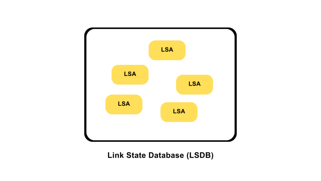
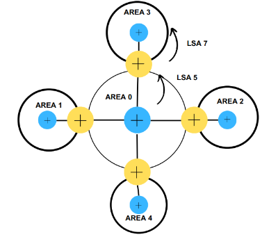
Since Stub areas contain Type 1, Type 2, and in some cases, Type 3 LSAs, which describe routers, network links, and summary routes within the area and a default route, the LSA flooding is reduced to a minimum, Link State Database becomes smaller which further leads to the smaller routing table and a smaller number of SPF calculations.
What are the different OSPF Stub Area types?
The different OSPF Stub Area types are as follows-
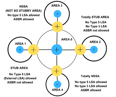
STUB AREA
This is the standard Stub area in which Type-5 LSA is blocked. Since it blocks all the type-5 LSA, routes that are redistributed into the OSPF are rejected in this area. Also, in the stub area, no ASBR is allowed, i.e. we cannot configure an ASBR into the stub area. This makes sense since we are not interested in receiving LSA Type-5, which means we do not require a router that generates Type-5 LSA, which is ASBR. Further, the Stub area uses a default route provided by the Area Border Router (ABR) to reach external destinations.
Totally Stub Area
Totally Stub area along with blocking all the Type-5 LSA, also prevents the advertisement of TYPE-3 LSA i.e., it does not allow summary LSA to enter into the area which further reduces the routing table. In the Totally Stub area, no ASBR is allowed.
NSSA
NSSA, also known as Not-So-Stubby Area, blocks Type-5 LSA, but ASBR routers are allowed in this area.
However, the ASBR router does generate the Type 5 LSA. It sounds contradicting, isn’t it?
Yes, it is contradicting. Not-So-Stubby Areas (NSSAs) are designed for situations where you need to introduce external routes (Type-5 LSAs) into a stub area without converting it into a standard OSPF area.
NSSA routers convert Type-5 LSA into the Type-7 external LSA. Type-7 LSA are only understood by NSSA and Totally NSSA. It gets converted to Type-5 LSA when it leaves an NSSA by Area Border Router. Similarly, when Type-5 LSA gets into the NSSA, it gets converted to Type-7 LSA so that routers in the NSSA can understand and get the routing updates.
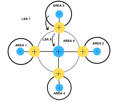
Totally NSSA
A total Not-So-Stubby Areas is an extension of the NSSA. In the case of Totally Not-So-Stubby Areas, not only are external routes (Type 5 LSAs), but Type 3 (Summary) LSAs are also suppressed, making it similar to a stubby area in terms of routing information. The only difference is that it allows ASBR.
It also works using the same concept as discussed in the case of NSSA.
Totally NSSA routers convert the Type 5 LSA to Type 7 LSA so that they can read the Link State Advertisements and update the routing table accordingly.
These areas are used to further optimize the routing by reducing and minimizing the routing table and blocking the routes that are not needed but, it is important to note that in the case of these areas, we always use the default route at Area border routers to reach a particular prefix outside the area when needed.
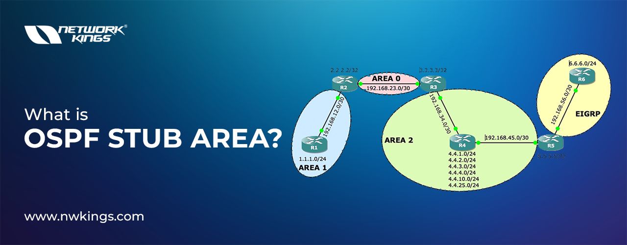
Configuration: -
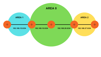
R1
R1#conf t
R1(config)#int fa0/0
R1(config-if)#ip add 192.168.15.5 255.255.255.0
R1(config-if)#no shutdown
R1(config-if)#ip ospf 1 area 1
R1(config)#int lo 0
R1(config-if)#ip add 10.5.5.5 255.255.255.0
R1(config-if)#ip ospf 1 area 1
R1(config)#Router ospf 1
R1(config-router)#router-id 10.5.5.5
R2
R2#conf t
R2 (config)#int fa1/0
R2(config-if)#ip add 192.168.10.1 255.255.255.0
R2(config-if)#no sh
R2(config-if)#ip ospf 1 area 0
R2 (config)#int fa0/0
R2(config-if)#ip add 192.168.15.1 255.255.255.0
R2(config-if)#no sh
R2(config-if)#ip ospf 1 area 1
R2 (config)#int lo 0
R2(config-if)#ip add 10.1.1.1 255.255.255.0
R2(config-if)#ip ospf 1 area 0
R2(config)#Router ospf 1
R2(config-router)#router-id 10.1.1.1
R3
R3#conf t
(config)#int fa1/0
(config-if)#ip add 192.168.10.10 255.255.255.0
(config-if)#no sh
(config-if)#ip ospf 1 area 0
R3(config)#int fa0/0
R3(config-if)#ip add 192.168.20.10 255.255.255.0
R3(config-if)#no sh
R3(config-if)#ip ospf 1 area 0
R3(config)#int lo 0
R3(config-if)#ip add 10.10.10.10 255.255.255.0
R3(config-if)#ip ospf 1 area 0
R3(config)#Router ospf 1
R3(config-router)#router-id 10.10.10.10
R4
R4#conf t
R4(config)#int fa0/0
R4(config-if)#ip add 192.168.20.2 255.255.255.0
R4(config-if)#no sh
R4(config-if)#ip ospf 1 area 0
R4(config)#int fa1/0
R4(config-if)#ip add 192.168.27.2 255.255.255.0
R4(config-if)#no sh
R4(config-if)#ip ospf 1 area 2
R4(config)#int lo 0
R4(config-if)#ip add 10.2.2.2 255.255.255.0
R4(config-if)#ip ospf 1 area 0
R4(config)#Router ospf 1
R4(config-router)#router-id 10.2.2.2
R5
R5#conf t
R5(config)#int fa1/0
R5(config-if)#ip add 192.168.27.7 255.255.255.0
R5(config-if)#no sh
R5(config-if)#ip ospf 1 area 2
R5(config)#int lo 0
R5(config-if)#ip add 10.7.7.7 255.255.255.0
R5(config-if)#ip ospf 1 area 2
R5(config)#Router ospf 1
R5(config-router)#router-id 10.7.7.7
Now, let us redistribute some routes on R3 so that it becomes an ASBR.
R3
R3 (config)#int lo 1
R3(config-if)#ip add 172.16.50.1 255.255.255.0
R3(config-if)#int lo 2
R3(config-if)#ip add 172.16.51.1 255.255.255.0
R3(config)#router ospf 1
R3(config-router)#redistribute connected subnets
R1#show ip route
Codes: L – local, C – connected, S – static, R – RIP, M – mobile, B – BGP
D – EIGRP, EX – EIGRP external, O – OSPF, IA – OSPF inter area
N1 – OSPF NSSA external type 1, N2 – OSPF NSSA external type 2
E1 – OSPF external type 1, E2 – OSPF external type 2
i – IS-IS, su – IS-IS summary, L1 – IS-IS level-1, L2 – IS-IS level-2
ia – IS-IS inter area, * – candidate default, U – per-user static route
o – ODR, P – periodic downloaded static route, H – NHRP, l – LISP
+ – replicated route, % – next hop override
The Gateway of last resort is not set.
10.0.0.0/8 is variably subnetted, 5 subnets, 2 masks
O IA 10.1.1.1/32 [110/2] via 192.168.15.1, 00:20:04, FastEthernet0/0
O IA 10.2.2.2/32 [110/4] via 192.168.15.1, 00:11:22, FastEthernet0/0
C 10.5.5.0/24 is directly connected, Loopback0
L 10.5.5.5/32 is directly connected, Loopback0
O IA 10.7.7.7/32 [110/5] via 192.168.15.1, 00:08:54, FastEthernet0/0
172.16.0.0/24 is subnetted, 2 subnets
O E2 172.16.20.0 [110/20] via 192.168.15.1, 00:01:55, FastEthernet0/0
O E2 172.16.51.0 [110/20] via 192.168.15.1, 00:01:28, FastEthernet0/0
O IA 192.168.10.0/24 [110/2] via 192.168.15.1, 00:20:04, FastEthernet0/0
192.168.15.0/24 is variably subnetted, 2 subnets, 2 masks
C 192.168.15.0/24 is directly connected, FastEthernet0/0
L 192.168.15.5/32 is directly connected, FastEthernet0/0
O IA 192.168.20.0/24 [110/3] via 192.168.15.1, 00:15:46, FastEthernet0/0
O IA 192.168.27.0/24 [110/4] via 192.168.15.1, 00:11:40, FastEthernet0/0
Notice that LSA Type 5 is present in its routing table.
Configure Stub Area:-
R1 (config)#router ospf 1
R1(config-router)#area 1 stub
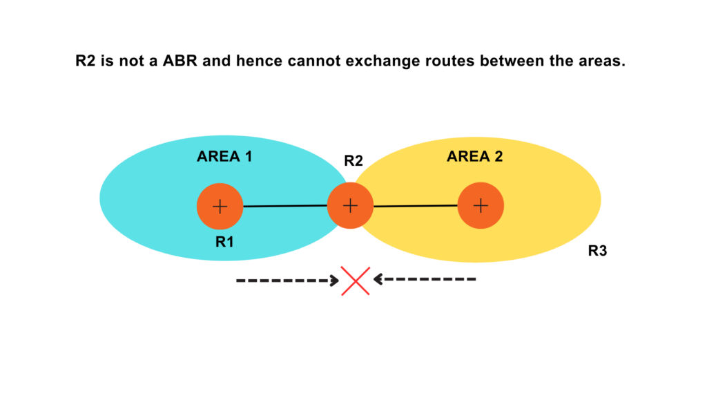
As soon as we configure the stub area on one router, OSPF neighborship goes down. Since stubs should be configured on all the routers in an area.
Hence, we will configure it on R2.
R2 (config)#router ospf 1
R2(config-router)#area 1 stub
R1#show ip route
Codes: L – local, C – connected, S – static, R – RIP, M – mobile, B – BGP
D – EIGRP, EX – EIGRP external, O – OSPF, IA – OSPF inter area
N1 – OSPF NSSA external type 1, N2 – OSPF NSSA external type 2
E1 – OSPF external type 1, E2 – OSPF external type 2
i – IS-IS, su – IS-IS summary, L1 – IS-IS level-1, L2 – IS-IS level-2
ia – IS-IS inter area, * – candidate default, U – per-user static route
o – ODR, P – periodic downloaded static route, H – NHRP, l – LISP
+ – replicated route, % – next hop override
The Gateway of last resort is 192.168.15.1 to network 0.0.0.0
O*IA 0.0.0.0/0 [110/2] via 192.168.15.1, 00:00:13, FastEthernet0/0
10.0.0.0/8 is variably subnetted, 5 subnets, 2 masks
O IA 10.1.1.1/32 [110/2] via 192.168.15.1, 00:00:13, FastEthernet0/0
O IA 10.2.2.2/32 [110/4] via 192.168.15.1, 00:00:13, FastEthernet0/0
C 10.5.5.0/24 is directly connected, Loopback0
L 10.5.5.5/32 is directly connected, Loopback0
O IA 10.7.7.7/32 [110/5] via 192.168.15.1, 00:00:13, FastEthernet0/0
O IA 192.168.10.0/24 [110/2] via 192.168.15.1, 00:00:13, FastEthernet0/0
192.168.15.0/24 is variably subnetted, 2 subnets, 2 masks
C 192.168.15.0/24 is directly connected, FastEthernet0/0
L 192.168.15.5/32 is directly connected, FastEthernet0/0
O IA 192.168.20.0/24 [110/3] via 192.168.15.1, 00:00:13, FastEthernet0/0
O IA 192.168.27.0/24 [110/4] via 192.168.15.1, 00:00:13, FastEthernet0/0
See the magic- Type 5 LSA, i.e., O E2 routes are blocked. Also, the default route is now present in the table.
Totally Stub:-
R4 (config)#router ospf 1
R4(config-router)# area 2 stub no-summary
R5 (config)#router ospf 1
R5(config-router)# area 2 stub no-summary
R5#show ip route
Codes: L – local, C – connected, S – static, R – RIP, M – mobile, B – BGP
D – EIGRP, EX – EIGRP external, O – OSPF, IA – OSPF inter area
N1 – OSPF NSSA external type 1, N2 – OSPF NSSA external type 2
E1 – OSPF external type 1, E2 – OSPF external type 2
i – IS-IS, su – IS-IS summary, L1 – IS-IS level-1, L2 – IS-IS level-2
ia – IS-IS inter area, * – candidate default, U – per-user static route
o – ODR, P – periodic downloaded static route, H – NHRP, l – LISP
+ – replicated route, % – next hop override
Gateway of last resort is 192.168.27.2 to network 0.0.0.0
O*IA 0.0.0.0/0 [110/2] via 192.168.27.2, 00:00:20, FastEthernet1/0
10.0.0.0/8 is variably subnetted, 2 subnets, 2 masks
C 10.7.7.0/24 is directly connected, Loopback0
L 10.7.7.7/32 is directly connected, Loopback0
192.168.27.0/24 is variably subnetted, 2 subnets, 2 masks
C 192.168.27.0/24 is directly connected, FastEthernet1/0
L 192.168.27.7/32 is directly connected, FastEthernet1/0
See, in a totally stub area, even the LSA-3 is filtered.
NSSA and Totally NSSA can be configured using the following commands-
Syntax to configure NSSA
R(config)#router ospf 1
R(config-router)#area 1 nssa
Syntax to configure Totally NSSA
R(config)#router ospf 1
R(config-router)# area 1 nssa no-summary