Network Kings

LIMITED TIME OFFER

$999 $499 only For All Access Pass Today! USE PROMO CODE : LIMITED

d :
h :
m

Inter VLAN Routing: Explained

inter vlan routing
inter vlan routing

Before talking about Inter VLAN routing, let me give you a brief introduction to VLAN first.

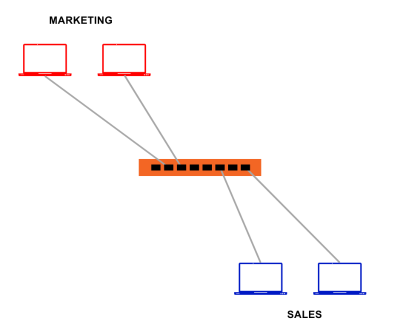
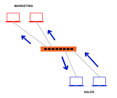
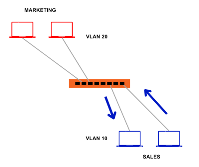
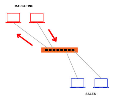
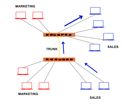
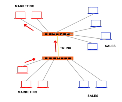
VLAN is a logical grouping of network devices connected to a switch. VLANs are used to create smaller broadcast domains at layer 2 by assigning different ports to different subnetworks on the same switch so that two or more departments cannot communicate with each other which helps to reduce unnecessary traffic in a network. Also, the use of VLAN in an organization is a common practice. This allows different departments to remain isolated from each other and saves bandwidth.

But what if two different VLANs or we can say two different departments of an organization want to communicate with each other? Can this be made possible?

What is Inter VLAN routing?

Inter VLAN routing is the process of enabling communication between devices on different VLANs within the same network. Without inter VLAN routing, devices on separate VLANs are essentially isolated from each other, unable to exchange data or access resources. Inter VLAN routing helps to resolve this communication gap by allowing data to flow between VLANs. To allow communication between different VLANs we take the help of routing and hence we need a device that can perform routing i.e., router or layer 3 switches.

Why is Inter-VLAN routing used?

As we discussed Inter VLAN routing can help to build a communication channel between two or more different VLANs, but besides this, it also has some other uses: –

  • Security

VLANs are used to enhance security by keeping sensitive data on a separate VLAN and ensuring that no unauthorized devices can access it. Inter-VLAN helps authorized devices access these resources and data. 

  • Shared Resources

Inter VLAN routing allows devices on different VLANs to share network resources efficiently. For instance, printers, file servers, and network-attached storage (NAS) devices can be placed on a separate VLAN; users from multiple VLANs can access these shared resources. This simplifies resource management and utilization. 

  • Scaling and Growth

As an organization grows, the network grows and new services are added, inter VLAN routing can help maintain efficient communication between VLANs without physically reconfiguring the network. 

  • Traffic Management and Optimization

By routing traffic between VLANs, you have control over how traffic flows within your network. This allows you to optimize network performance and ensure that bandwidth is allocated according to the organization’s needs and policies. 

How does Inter-VLAN routing work?

Inter VLAN routing can be implemented using three methods, namely- 

  • External Router

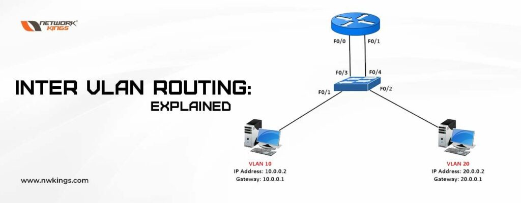
The oldest method of implementing Inter VLAN routing is using a router with multiple interfaces and each router interface is connected to ports on a switch configured with different VLAN. The router interface acts as a default gateway for the particular VLAN. 

An example of this method is shown in the diagram below. 

Ports on the switch are assigned to particular VLANs as mentioned and each port is connected to the port on the RE. When a PC in VLAN 10 wants to communicate with a PC configured at VLAN 20, the packet is forwarded to the default gateway of VLAN 10 i.e., Gi0/0. The router examines the destination address and sends out a packet to the Gi0/1 interface. A packet that travels to the fa0/2 port of the switch and finally reaches PC 2 i.e., PC configured with VLAN 20. 

External Router

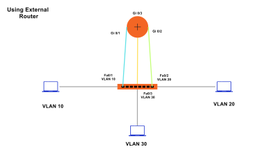
This method is effective but it has a drawback. Since each VLAN requires a different default gateway and hence different RE ports. It becomes a costly method. RE used to have a smaller number of ports. In our example, we had only three VLANs. What is an organization that has 10 different departments and requires 10 different VLANs?  

Hence this solution is not scalable. 
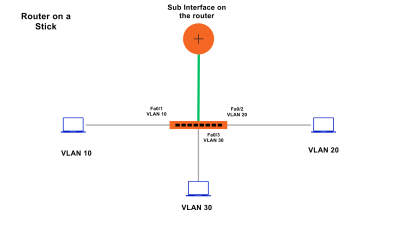
  • Router-on-a-Stick

As we saw in the case of the old Inter-Vlan routing method we require ports equal to the number of VLAN configured in a network but the router-on-the-stick method overcomes this drawback. 

NOTE: In the case of the Router-on-a-stick method we only require one physical Ethernet interface. 

But, how is it possible to enable it using a single port?

The router uses the concept of Sub-Interfaces, each associated with a specific VLAN. These Sub-Interfaces are assigned IP addresses, acting as the default gateways for devices in their respective VLANs. VLAN tagging (usually with 802.1Q) is employed to differentiate traffic from different VLANs as it passes through the single physical connection to the router. This router port is connected to the layer 2 switch trunk port.

When a packet tagged with a VLAN enters the router sub-interface, the router makes the routing decision based on the destination IP Address and then it determines the exit interface for that particular packet. Since the exit sub-interface is also configured as an 802.1Q sub-interface, the new VLAN is tagged at the data frames and forwarded accordingly.

Router-on-a-Stick

This method is cost-effective since it requires only one physical router. However, it can also become a bottleneck if there is a significant amount of inter-VLAN traffic since all the traffic must pass through a single physical interface. Since it employs the use of a single physical interface, latency is also high. Also, if this physical interface goes down for any reason, an outage in a network can occur. 

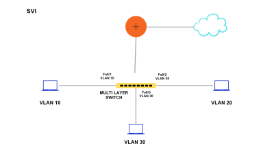
  • Switch Virtual Interface/ Use of Layer 3 Switch

A Layer 3 switch, also known as a multilayer switch, combines the features of a traditional network switch and a router. A layer 3 switch is also known as a multi-layer switch since it can operate on both layer 2 and layer 3. We can configure a switched virtual interface on a layer 3 switch.  

it has VLAN interfaces configured for each VLAN and can route traffic between these VLANs using the physical interfaces connected to the switch. 

Devices within each VLAN use the Layer 3 switch as their default gateway. DVI performs the same function for the VLAN as a router sub-interface does but it is much faster than it since it employs the same hardware for routing and switching. This method is also not limited to one link because the concept of EtherChannel can also be used between switches to increase the bandwidth. Latency is also lower in SVI. 

SVI

This approach is efficient and provides high-speed inter VLAN routing because it eliminates the need for a separate physical router. The main disadvantage of using this method is the cost. Generally, Multi-Layer switches are expensive devices.

Also, the configuration for Multi-Layer switches is a little complex.

What is VLAN? – Know in Detail 

what is vlan

Suppose we have two departments in an organization- Sales and Marketing, connected as shown in the figure  

vlan

The sales PC wants to broadcast a message for its department while the message has nothing to do with the marketing department, but what should the switch do in such circumstances? 

Yes, it broadcasts that message to each PC connected to it; hence, the marketing PC will also be reading that particular message.

A diagram illustrating the collaboration between marketing and sales.

Does it sound good?  

Apart from unnecessary network congestion occurring due to broadcast, there is a layer two attacks risk.  

One of the solutions is to buy different switches for each department and connect them accordingly.  

But, with this approach, three problems arise-  

  • Cost of the infrastructure increases.  
  • A lot of switch ports might remain vacant.  
  • What if one department wants to communicate with another department? We need to broadcast that message individually for each department.  

Thus, VLAN is the concept that can help to eliminate all these problems.

What is VLAN?

what is vlan

VLAN is a logical grouping of network devices connected to a switch. By creating VLAN, we create smaller broadcast domains at layer-2 by assigning different ports to different subnetworks on one switch. 

In simple words, we are creating a small LAN inside a LAN.  

With the help of VLAN, frames broadcasted get switched between ports and groups within the same VLAN.

So now, let us assign VLAN 10 to Sales and VLAN 20 to Marketing, as shown in the figure.

Now if the Sales PC sends out the broadcast packet, it will also reach another Sales PC or the PCs assigned with VLAN 10.  

Similar is the case with Marketing PCs. Whenever a Marketing PC broadcasts a message, it will reach the PCs with VLAN 20. 

vlan
A visual representation illustrating the collaboration between marketing and sales in a company.

VLAN ranges from 0-4095  

  • VLAN 0 and 4095 are reserved for system use only.   
  • 01 is the default VLAN. Initially, each port is in VLAN 1  
  • 2-1001 are Ethernet VLANs and can be assigned and deleted  
  • 1002-1005 are Cisco defaults used for FDDI and Token Ring. It cannot get deleted. 
  •  1006-4094 are called extended VLANs. 

Let us understand the basic VLAN configuration:

Initially, ports and VLAN of a switch look like this- 


Switch> en 

Switch# show vlan 


VLAN Name Status Ports 

—- ——————————– ——— ——————————- 

1 default active Fa0/1, Fa0/2, Fa0/3, Fa0/4 

Fa0/5, Fa0/6, Fa0/7, Fa0/8 

Fa0/9, Fa0/10, Fa0/11, Fa0/12 

Fa0/13, Fa0/14, Fa0/15, Fa0/16 

Fa0/17, Fa0/18, Fa0/19, Fa0/20 

Fa0/21, Fa0/22, Fa0/23, Fa0/24 

Gig0/1, Gig0/2 


1002 fddi-default active  

1003 token-ring-default active  

1004 fddinet-default active  

1005 trnet-default active

Configuration

Switch(config)#vlan 10 

Switch(config-vlan) #name sales 

Switch(config)#interface fa0/1 

Switch(config-if) #switchport access vlan 10 

Switch(config-if) #interface fa0/2  

Switch(config-if) #switchport access vlan 10 

Switch(config)#interface fa0/1 

Switch(config-if) #switchport access vlan 10 

Switch(config-if) #interface fa0/2  

Switch(config-if) #switchport access vlan 10 


Switch#show vlan 


VLAN Name Status Ports 

—- ——————————– ——— ——————————- 

1 default active Fa0/5, Fa0/6, Fa0/7, Fa0/8 

Fa0/9, Fa0/10, Fa0/11, Fa0/12 

Fa0/13, Fa0/14, Fa0/15, Fa0/16 

Fa0/17, Fa0/18, Fa0/19, Fa0/20 

Fa0/21, Fa0/22, Fa0/23, Fa0/24 

Gig0/1, Gig0/2 


10 sales active Fa0/1, Fa0/2 

20 marketing active Fa0/3, Fa0/4 


1002 fddi-default active  

1003 token-ring-default active  

1004 fddinet-default active  

1005 trnet-default active 


Port Fa0/1 and Fa0/2 are part of VLAN named Sales.  

Port Fa0/1 and Fa0/2 are part of VLAN named Marketing. 

What is a Trunk Port?

In our previous example, all PCs of the different departments get connected to the same switch, but what if we have more than one switch connecting PCs of diverse departments? Also, the PCs of the same department get connected to different switches. 

Let’s say two Sales and three Marketing employees are on floor number 1 while four employees of Sales and two of Marketing are sitting on floor number 2.

Sales VLAN: – 10  

Marketing VLAN: – 20

The switch on floors 1 and 2 are connected using a link.  

Therefore, we have learned that each port gets configured as VLAN 1. But now, can the Sales PC on floor 1 communicate with Sales PC on floor 2?

Of course not, because the link connecting both switches gets configured as VLAN 1. 

One option is to configure it on VLAN 10 so that the Sales PC can communicate, but, in this case, Marketing PC will not be able to communicate further; and vice versa is also possible.

To overcome this problem, we use Trunk Ports. 

Access Port: – Port which carries the traffic of only 1 VLAN. Traffic is sent and received on a trunk port without any tagging, and if there is traffic while tagging (IEEE 802.1Q tagged), it will just drop the packet.

Trunk Port: – The port which allows traffic of different VLANs to pass through it. 

Switch 1

Switch>en 

Switch#config t 

Switch(config)#vlan 10 

Switch(config-vlan)#name SALES 

Switch(config-vlan)#vlan 20 

Switch(config-vlan)#name MARKETING 

Switch(config-vlan)#interface range fa0/2-3 

Switch(config-if-range)#switchport access vlan 10 

Switch(config-if-range)#interface range fa0/4-6 

Switch(config-if-range)#switchport access vlan 20 

Switch(config-if-range)#exit 


Switch# Show VLAN 


VLAN Name Status Ports 

—- ——————————– ——— ———————- 

1 default active Fa0/1, Fa0/7, Fa0/8, Fa0/9 

 Fa0/10, Fa0/11, Fa0/12, Fa0/13 

Fa0/14, Fa0/15, Fa0/16, Fa0/17 

Fa0/18, Fa0/19, Fa0/20, Fa0/21 

Fa0/22, Fa0/23, Fa0/24, Gig0/1 

Gig0/2 

10 SALES active Fa0/2, Fa0/3 

20 MARKETING active Fa0/4, Fa0/5, Fa0/6 

1002 fddi default active  

1003 token-ring- default active  

1004 fddinet default active  

1005 trnet default active

Switch 2

Switch#config t 

Switch(config)#vlan 10 

Switch(config-vlan)#name SALES 

Switch(config-vlan)#vlan 20 

Switch(config-vlan)#name MARKETING 

Switch(config)#interface range fa0/2-5 


Switch(config-if-range) #switchport access vlan 10 

Switch(config-if-range)#interface range fa0/6-7 

Switch(config-if-range)#switchport access vlan 20 


Switch#show vlan 


VLAN Name Status Ports 

—- ——————————– ——— ——————————- 

1 default active Fa0/1, Fa0/8, Fa0/9, Fa0/10 

Fa0/11, Fa0/12, Fa0/13, Fa0/14 

Fa0/15, Fa0/16, Fa0/17, Fa0/18 

Fa0/19, Fa0/20, Fa0/21, Fa0/22 

Fa0/23, Fa0/24, Gig0/1, Gig0/2 

10 SALES active Fa0/2, Fa0/3, Fa0/4, Fa0/5 

20 MARKETING active Fa0/6, Fa0/7 

1002 fddi default active  

1003 token-ring- default active  

1004 fddinet default active  

1005 trnet default active

Trunk:

Switch 1 

Switch(config)#interface fa0/1 

Switch(config-if)#switchport mode trunk 

Switch(config)#interface fa0/1 

Switch(config-if)#switchport mode trunk 

NOTE: – Older switches support both .1q and ISL encapsulation, but the new switch model only supports .1Q encapsulation.  

In the case of an older switch, an extra command (Switch(config-if)# switchport trunk encapsulation dot1q) is mandatory to define the encapsulation type.

Switch 2 

Switch(config)#interface fa0/1 

Switch(config-if)#switchport mode trunk 

Switch(config)#interface fa0/1 

Switch(config-if)#switchport mode trunk 

A diagram of a marketing and sales funnel illustrating how VLANs work.
A diagram illustrating a marketing and sales network.

Now if PC 1 wants to communicate with PC 2, it will send a message. The message gets received on Switch-1 and transmitted with the link connected on Fa0/1 to Switch-2 since we configured Port Fa0/1 as a trunk port on both switches. Hence it can pass traffic of all VLANs.

Similarly, If Marketing PC wants to communicate with Marketing PC on the 2nd floor, the switch can transmit the frame with the link connected to Fa0/1 to Switch 2. In this way, the trunk port can help ship frames of different VLANs using a single port.

Another question that strikes me is how the port at the trunk port and other ports knows which frame is of which VLAN.   

Switch knows about the type of VLAN using encapsulation.  

What is encapsulation and its types?

When the switch port gets configured as Trunk Port, it adds a unique ID to frames to identify their VLAN, known as encapsulation.  

There are two types of encapsulations-  

  • IEEE802.1Q 
  • Inter-Switch Link (ISL) 

Difference between IEEE802.1Q and Inter-Switch Link (ISL)-

802.1Q is a standard and multivendor protocol, while ISL is Cisco proprietary. Also, ISL does not get supported by other switches.  

ISL adds a 30-byte size of the tag to identify the VLAN, while 802.1Q adds only 4 bytes to perform a similar function.

Conclusion!

We have understood a fatal problem faced in an organization having different departments and the solution to it. VLAN helps to group devices of diverse departments which helps to reduce the cost of the infrastructure and makes network management easy.

If a different department wants to communicate with the other, then it can be achieved by using a router, and this concept is known as Inter-VLAN Routing.